Maximum Power Point Tracking Circuit Driven by an Arduino
| ✅ Paper Type: Free Essay | ✅ Subject: Physics |
| ✅ Wordcount: 2333 words | ✅ Published: 23 Sep 2019 |
Progress Report
MPPT circuit driven by an Arduino
1.ABSTRACT:
MPPT (Maximum Power Point Tracking) are electronic devices that Engineers are designing, making and improving to get the maximum power out of solar panels at various condition.
As we all know, most of the energy currently consumed comes from the use of fossil fuels like oil, coal, natural gas or even nuclear energy. Recent studies and forecasts inform us that
the massive use of these resources will certainly lead to the total depletion of these
reserves. In addition, everyone is globally convinced by the danger of this process
on the environment.
From this observation, it was necessary to look for other energy resources. renewable (Green) energies such as photovoltaic and wind are alternatives, they are becoming more and more used in our days. This type of energy is not only free and inexhaustible, but also very clean for the environment. Moreover, we often talk about “Green”, an energy
witch completely avoids polluting the Earth compared with traditional sources [1]
Power grid distribution networks cannot be enough to provide electricity to the entire world population whether they are in the mountains or on an island, in the less inhabited or in the middle of the desert, sites that are difficult to access or very isolated cannot always be connected to the grid for lack of technical solutions or economic viability. Whereas (PV) panel can be implemented in any remote areas.

Solar Energy is one of the greener renewable form of power widely used today. However, harvesting this source to the maximum can be very challenging as there are many factors to consider.
MPPT (Maximum Power Point Tracking) are electronic devices that Engineers are designing, making and improving to get the maximum power out of solar panels at various conditions. The objective of this work was to design and build an MPP Tracking circuit for a photovoltaic panel system that uses (DC/DC) Buck converter based on an Arduino Uno Board. The Algorithm Perturb and Observe( P&O) was implemented to compute and track the maximum power of the Solar panel at any given voltage inputs ranging from 23V to 70V DC. The circuit was simulated on MATLAB . for analysis and built and tested on a PV simulator in the Lab.
The aim is to illustrate the importance Of an MPPT device in increasing the Power
efficiency of PV panels by
- Identifying different components of the MPPT
- List the various Algorithm used to track the maximum power
- Build MPPT circuit
- Implement two MPPT algorithms, compare and analyse the efficiency
- Draw a conclusion
To illustrate the importance of MPPT devices and for designing ,making an MPPT circuit for solar panel,this project is divided into different activities each activity is given a specific time frame and task.
the following activities adopted are:
Activity 1:
- literature review of photovoltaic system is important to understanding the concept and the working condition of solar cells
- importance of MPPT devices
- highlight the different MPPT algorithms used and their advantages and disadvantages
- different MPPT circuit used and the proposed Buck converted circuit will be investigated and the components choice justified.
Activity 2:
Identify the different components of an MPPT:
- Build a Buck converter Circuit and test its functionality
- Voltage sensor used
- Current sensor type
- Microcontroller (Arduino Board)
Activity 3:
Build and test the MPPT circuit
- Checking the performance of the built MPPT circuit under a different irradiance condition
- Compare the Perturb and Observe (P&O) algorithm with a fixed set algorithm
- MATLAB simulation of the built circuit
Activity 4:
- Highlight any issues and any improvement to the circuit
- Draw a conclusion
5.Literature Survey/Theory:
Photovoltaic cell
A photovoltaic cell is an opto-electrical component that transforms solar light into electricity, discovered by E. Becquerel in 1839.Photovoltaic cell consists of a P-N type semiconductor material. linked together to form a p-n junction .this will form an electric field in the region of the junction as electrons jump to the positive p-side and holes shift to the negative n-side[5]
photons in the sun light, cause the electrons in the PV Cell to jump to a higher energy state known as the conduction band. In their new state, these electrons are free to move through the material, this motion of the former generates an electric current in the Photovoltaic cell.
Since that time work have been made to improve efficiency and make affordable solar cells. Figure (1.1) represents a sample configuration of the photovoltaic cell.
https://energyeducation.ca/encyclopedia/Photovoltaic_cell
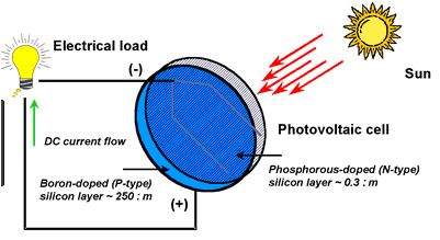
Figure (1.1): Diagram of a photovoltaic cell
https://www.quora.com/What-is-a-PV-cell
Photovoltaic effect
solar energy comes from the direct transformation of part of the solar radiation into electrical energy. This energy conversion is done through a cell called photovoltaic based on a physical phenomenon named photovoltaic effect system which consists in producing an electromotive force when the surface of this cell is exposed to light [1] [2].
The elementary photovoltaic cell creates a very low power generator. A cell only ten centimeters square delivers at most, a few watts at a voltage less than one volt [ 3].
To produce more power, several cells must be assembled in order to create a module or a photovoltaic field. The serial connection of the cells allows to easily increase the voltage of the set, while parallel connection increases the current Serial / parallel wiring is therefore used to obtain an overall PV generator with the desired characteristics.
Photovoltaic module
The most crucial component of any PV installation is the photovoltaic module, which consists of interconnected solar cells. These modules are connected to each other to form power (station fields) so that they can satisfy different levels of energy needs. Figure (1.2) shows a photovoltaic module.
More and more powerful modules are available on the market, especially for the
network connection, but there is still a limit related to weight and manipulation.
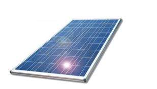
Figure (1.2): Photovoltaic Module
Photovoltaic power station
The photovoltaic power station consists of photovoltaic modules interconnected in
series and in parallel in order to produce the required power. These modules are mounted on a metal frame with an angle of inclination for a better power outcome
Figure (1.3) shows a photovoltaic power station.
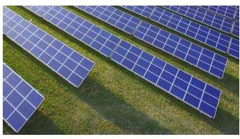
Figure (1.3) Photovoltaic Power Station
1.3 Photovoltaic Modeling
1.3.1 Ideal photovoltaic model
The photovoltaic module can be represented by its equivalent electrical circuit
given by figure (1.4)
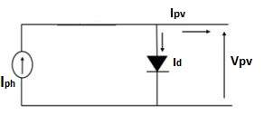
Figure (1.4): Ideal circuit of the PV cell
This circuit is composed of a current generator source which produces a current proportional to the incident sun light power, a parallel diode which corresponds to the transition area P-N junction of the PV module [4].
The current generated by the module is mathematically written to describes the Current and voltage (I-V) characteristic.

Id
symbols are defined as follows
- Ipv Output current of the cells (directly proportional to the Sun irradiation).
- Id diode equation.
- q the electron charge (1.60217646 × 10⁻¹⁹ C).
- k Boltzmann constant (1.3806503 × 10⁻²³ J/K).
- I0 cell is the reverse saturation or leakage current of the diode.
- Iph function of irradiation level and junction temperature (5 A).
- T the temperature of the p–n junction (in Kelvin).
- A diode ideality constant. e: electron charge (1.602 × 10⁻¹⁹ C).
- Ic cell output current (A).
- I0 reverse saturation current of diode (0.0002 A).
- Tc reference cell operating temperature (20 °C).
- Vc: cell output voltage ( V).
- Rs series resistance of cell (0.001 Ω).
1.3.2 Real photovoltaic model
In the real case, there is a loss of voltage at the output as well as currents leakage
thus, the previous photovoltaic model did not account for all the phenomena
present during the conversion of sun light energy. We model this voltage loss
by series resistance and leakage currents by parallel resistance [4]. The
figure (1.5) represents equivalent electrical diagram of a real photovoltaic module.
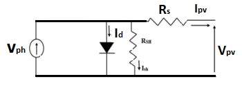
Figure (1.5): real circuit of the PV cell
The current generated by the PV module is given by Kirchhoff’s law
is the current supplied by the PV module.
is the photo- current depending on the illumination (G)
K is the Boltzmann constant (1.381 joule / Kelvin)
q is the electron charge = 1.602*
C.
T is the temperature of the PV module in kelvin.
A is the ideality factor of the junction (1 <A <2).
1.4 Electrical parameters of the photovoltaic module
The different parameters characterising a photovoltaic module are the open voltage circuit. Short circuit current, maximum power, Fill Factor and efficiency.
They are extracted from current/voltage characteristics, they are used to compare different Pv modules when illuminated under identical conditions.
1.4.1 Open circuit voltage
when a PV module is placed under a constant light source without any current flow, no load connected we obtain at its terminals a maximum continuous voltage, called open circuit voltage
.
where 0.6 V is the voltage for an elementary PV cell and N is the number of cells. We measure
by directly connecting a voltmeter to the terminals of the PV module [5].
1.4.2 Short circuit current
When the PV module is short-circuited, it delivers its maximum voltage current.
It is said short circuit current Icc. Its value is obtained by connecting an ammeter
at the terminals of the module. In silicon PV modules, the current is of the order of
12mA / cm² [5].
1.4.3 Maximum Power
The power supplied to the external circuit by a photovoltaic module depends on the load resistance (external resistance placed across the module).
This power is maximum (noted Pmax) for an operating point Pmax of the current-voltage (I/V) curve.
1.4.2 Fill Factor
The form factor is the ratio of the maximum power provided by the
PV module, and the product of the ICC short-circuit current by the voltage of
open circuit.is essentially a measure of quality of the solar cell.
1.4.3 Solar panel efficiency
It quantifies a solar panel (module) ability to convert sunlight into electricity
It’s given to be:
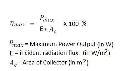
http://www.rfwireless-world.com/calculators/Solar-Cell-Efficiency-Calculator.html
2.3.4. Disturbance method and observation
The P & O control principle is to cause a low disturbance
value on the voltage, which generates a variation of the power. Figure (2.8) shows
that if an increase in voltage causes an increase in power, the point of
operation is to the left of the PPM, if on the contrary the power decreases, it is
right. In the same way, we can make a reasoning for a reduction of the tension.
In summary, for a voltage disturbance, if the power increases, the direction of the
disturbance is maintained. If not, it is reversed so that the operating point
converges towards the PPM [10].
Figure (2.8): Power-Voltage Characteristic of a Photovoltaic Module
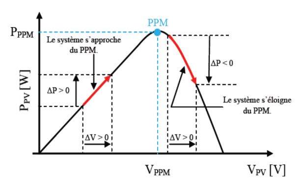
Figure (2.8): Power-Voltage Characteristic of a Photovoltaic Module
6.Progress Made:
(up to 5 pages)
Discuss the progress made during the first semester and include preliminary observations/results.
Work plan for the second semester (1 page)
Detail how the remainder of the project is to be carried out. Include a work plan.
References
Use the recommended format (either Harvard-SHU or APA 6) for more info see http://libguides.shu.ac.uk/referencing
Cite This Work
To export a reference to this article please select a referencing stye below:
Related Services
View all


DMCA / Removal Request
If you are the original writer of this essay and no longer wish to have your work published on UKEssays.com then please click the following link to email our support team:
Request essay removal