Real Time Implementation of Embedded Devices as a Security System in Intelligent Vehicles
| ✅ Paper Type: Free Essay | ✅ Subject: Mechanics |
| ✅ Wordcount: 3908 words | ✅ Published: 23 Sep 2019 |
Real time implementation of Embedded devices as a security system in Intelligent vehicles connected via Vanets.
|
Article Info |
ABSTRACT |
|
|
Article history: Received Jun 9, 2016 Revised Nov 20, 2016 Accepted Dec 11, 2016 |
The fast boom of technology has made our lives easier. The number of computer based functions embedded in cars have multiplied extensively over the past two decades. These days, many embedded sensors allowing localization and verbal exchange are being advanced to enhance reliability, protection and define new exploitation modes in intelligent guided transports. An in-car embedded electronic architecture is a complex setup machine, the improvement of that particular system is related to unique manufacturers and providers. There are several factors required in an efficient and secure system along with protection features, real time monitoring, reliability, robustness, and many other integrated features[1-2]. The appearance of modern era has also expanded the use of vehicles and its associated dangers. Dangers and the road accidents take place often which causes loss of lives and assets due to the bad emergency centres, lack of safety features and limitations within devices embedded within a vehicle. A rpm-speed calculating device can be used in a vehicle such that risku situations while driving can be detected. A system with Ultra sonic sensor can be used as a crash detector of the automobile in the course of the event and also after a crash. With indicators from the device, extreme coincidences also can be recognized. .As the amount of urban automobile grows automobile theft has become a shared difficulty for all citizens. As a solution an antitheft system can be implemented using PIR motion sensors where the system can be attached to the peripheral surface of the vehicle. When these sensors are interfaced with Arduino microcontroller an efficient and reliable security system can be developed[3]. |
|
|
Keyword: Embedded systems Vehicle security Microcontroller Sensors
|
||
|
|
||
- INTRODUCTION
The excessive demand of vehicles has elevated the user risks and road injuries. This design is a system which can discover obstacles in substantially less time and that can send the basic information to the driver within some seconds producing the noise signals as alerts. The primary goal of these activities is the growth of road protection and transportation efficiency, In addition to reducing the harmful effects of transportation on the external surroundings which can even be caused due to collisions. For instance, lowering the range of injuries can in turn lessen the number of visitor jams, which should reduce the level of damage on the Infrastructure. Due to the significance of those actions for both the individual and the system [4-6].
The Dramatic increase within the traffic waft raises call for on progressive technologies which can enhance protection and efficiency of transportation structures. Street safety may be substantially stronger with the aid of the deployment of speed calculating technologies for vehicular systems, which would allow the driver to control and regulate the speed of the vehicle and thus allow the driver to maintain the speed of the vehicle within the speed limit of any particular road. This can be of immense advantage for drivers particularly driving during the night time. As the population of urban vehicles grows unexpectedly with the improvement of the purchasing power of average citizens and improvement within the economy in a country, humans are becoming concerned about vehicle theft protection, which creates greater market opportunities for vehicle anti-theft systems. Numerous automobile anti theft devices have been designed with many advanced features, however the result remains disappointing due to the fact all these devices have its drawbacks. Domestic and distant places car anti-robbery products are primarily technologically classified into three categories which are mechanical lock devices, automobile alarm gadgets, and automobile tracking systems, chiefly aiming at stopping vehicles to be broken in and driven away.
The most generally used mechanical lock tool is a common wheel lock, which is extraordinarily reasonably-priced but inconvenient to use and at the same time can easily be disassembled by the professionals. These mechanical devices are often very bulky to handle and often very much inconvenient. A resolution to this problem would be to use Vehicle alarm gadgets which are very common these days. This is mostly because facts show that most of the public are conscious when they listen an alarm and also this makes the resident neighbours alerted as well. These vehicle alarm systems do have a massive range as well, some well designed can reach up to distances of up to 400 meters from the source of the alarm hence making it very hard for someone to steal a car with a motion detection alarm antitheft system[7], In cities as soon as the automobile is tried to access, the police will easily be notified by the antitheft alarm sounding from the device and the location of such a disturbance hence making it impossible for anyone to steal the vehicle. In addition to this having a car alarm can add additional benefits to the system which would include a fall in the insurance expenditure for the vehicle as security is one of the major constraint that authorities look into while providing insurance to any customer vehicle. Moreover, this will totally prevent the vehicle from the major risk of being stolen. Also it would improve the resale value of the vehicle.These days security alarm devices can be connected to smart phone applications and thus the user can easily monitor the activity of the vehicle from anywhere around making it easy and convenient.

The device that’s setup consists of a passive infra red(PIR) motion detection sensor which is attached to the system. The PIR motion detection sensor essentially calculates the Infra red light which is given out from things that are kept in its field of view. Within the PIR sensor system a pyro electric crystal is placed which would measure the heat that is given out from any object, and in case of humans the heat that’s given out from the human body. The heat energy is in fact emitted as radiations from any object. The hotter the object or a body the more the radiations or heat energy that’s dissipated from the body and these are transmitted in infra red wavelengths. Once these infra red waves enter the sensor it can essentially detect the presence of an object in its vicinity. A PIR sensor would record the movements from people around it. Once a person comes near the sensor there would be a kind of variation within the temperature that is sensed by the sensor as there would be difference between the body temperature and the room temperature. And once this difference is detected within the sensors field of range it can stimulate a change in voltage within its output which would result in producing alarm. A differential detection method is implemented by the PIR sensor. Usually the crystals and the sensors are covered by fresnel lenses which is transparent to IR waves and would prevent the chance of getting any false alarms that can be caused due to unwanted particles getting near the sensor. And also a fresnel lens can help to focus the IR waves to the sensor source. The variety of the accidents that’s occurring worldwide is increasing very rapidly but the amount of fatalities has reduced because of development of new generation devices developed by the automobile industry[8], Engineers had been chipping away on the surprising numbers of centres for a long term by designing air luggage and seat belts, more potent frame and special indoors designs to increase the protection of vehicles. However, the most effective way to secure a vehicle is to preserve vehicles from smashing into each other in the first place. To serve this purpose an obstacle detection gadget can be attached to the vehicle to prevent any kind of collision such that it can detect it way before the incident happens[9-10].
Obstacle detection gadget uses Ultra sonic sensor for distance calculation. Advanced driver assistance machine use radar because of its merits like longer detection range, angular position, variety and ensured safety. A vision primarily based sensor is implanted for detecting the obstacle and fending off collision. The two crucial parts, which is the navigation and the obstacle avoidance part are processed on the equal time growing the efficiency of the system. The important objective is to detect the obstacles present beforehand of the automobile. The device alarms the transferring car to prevent collision. In this system ultrasonic sensor is implanted for the detection purpose as they can stumble on the object from the shifting vehicle even as the distance among the automobile and obstacle is detected and the gap is also accurately measured. The obstacle detection system is interfaced with a system which would voice commands at the output such the user will be aware of the surroundings while driving and if any obstacle is found particular voice commands can help the driver to easily navigate the vehicle. This can be of immense help particularly while trying the park the vehicle in a secure location and also while driving through heavy traffic. This is achieved by connecting the microcontroller to an Arduino android shield which when connected to an Android device through Bluetooth can give out voice commands through the connected speaker [11-12].
To be able to avoid collision between the vehicles the sensor that is set up should measure the accurate distance from the obstacle and transmit the measured readings to the main component of the gadget. The ultrasonic sensor is hooked up in a manner in such that boundaries and obstacles which are present in the front side of the vehicle are being detected. The obstacles and objects which are present in the rear side is also detected by the ultrasonic sensors. One of the predominant part of this concept is to analyse any type of obstacle on the road. For instance, desk bound objects, human beings travelling that get in the passage of the vehicle can also be additionally taken into consideration as obstacles. Those objects are detected via the system and signals the car for secure and easy navigation. This brief process alerts the driver to respond very quickly. However there are a few drawbacks within the sensing technologies like failure in action in the presence of horrific weather conditions consisting of fog, snow and rain [13-14].
- RESEARCH METHOD
The Hardware requirements include :
- Arduino Microcontroller
- LED
- Buzzer
- PIR motion sensor
- Ultra sonic sensor
- LCD Display module 16×2
- Jumper cables
- IR sensor
- The Arduino shield
- Bluetooth connected andriod mobile phone
- 1Sheeld Android shield for Arduino
Software requirement :
- 1Sheeld application for Android.
A PIR motion sensor is an electronic device that would compute the Infra red waves that are emitted from objects which are present in its field of view and thus would identify any kind of motion that happens in front of the sensor. It’s very commonly used in antitheft alarm systems which can sense the movement of people in front of the sensor. Here the PIR sensor that’s present within the main device would recognise the quantity of IR waves which are falling on the device. As a person approaches the device there would be a variation within the temperature readings between the person’s body and the surroundings and this in turn can stimulate a voltage within the device which would give out alarm as the output.
An Ultra sonic sensor or a distance sensor would calculate the distance from the source using the waves, In particular the ultra sonic waves. The sensor would release ultra sonic waves and then it would collect the reflected waves from the source. Here time is used as a constraint to measure the time between the processes of emission and reception.
An IR sensor is primarily used to sense the surrounding objects and conditions. It makes use of the Infra red waves. Infra waves would essentially record the amount of heat given out from a particular object. The hotter the body, the more the heat will be given out from it. At the same time the IR sensor can also detect the motion which would happen in its field of view. Here an Infra red LED would be the emitter and the detector would be an IR photo diode.
A buzzer is an audio signalling device and are commonly used in alarms and which would come with a particular confirmation. There can be many different types of buzzers which can be mechanical, electromechanical or piezoelectric.
An Arduino shield is a modular and compact circuit boards which would enhance and add new features to the existing arduino system. There exists certain libraries which are associated with certain arduino shields with separate functionalities.
We make connections which include :
(I) For the RPM-speed calculation system
IR Sensor(dataPin) to Arduino(Pin 2)
IR Sensor(GND) to Arduino(GND)
IR Sensor(+Power) to Arduino (+5V)
LCD(Vss) to Arduino (GND)
LCD(Vcc) to Arduino (5V)
LCD(VEE) to Potentiometer
LCD(Rs) to Arduino (Pin 8)
LCD(Rw) to Arduino (Ground)
LCD(E) to Arduino (Pin 9)
LCD(DB4) to Arduino(Pin 4)
LCD(DB5) to Arduino(Pin 5)
LCD(DB6) to Arduino(Pin 6)
LCD(DB7) to Arduino(Pin 7)
LCD(LED+) to Arduino (+5V)
LCD(LED-) to Arduino (Ground)
(II) For the Anti theft motion detection system
PIR(GND) to Arduino (GND)
PIR(OUT) to Arduino (Pin 2)
PIR() to Arduino (+5V)
Buzzer red to Arduino (Pin 3)
Buzzer black to Arduino (GND)
LED (+ve) to Arduino (GND)
LED (-ve) to Arduino (Pin 3)
(III) For the Collision detection and avoidance system
Ultrasonic ECHO to Arduino Pin 3
Ultrasonic (GND) to Arduino Pin GND
Ultrasonic TRIG to Arduino Pin 8
Buzzer BLACK to Arduino Pin GND
Buzzer RED to Arduino Pin 6
Ultrasonic Vcc to Arduino Pin 5V
The Algorithm is given to be as following :
(I) The Operation of the rpm-speed calculation system
use pin 2,3,4,5,6,7 for lcd module
use pin 9 as sensorPin
use pin 11 as startPin
function delay(){
define int i,j
define count = 0
if (sensor > 0)
increment count
return count
}
function setup (){
set sensor as INPUT
set start as INPUT
set pin 2 to OUTPUT
lcd Print message (“Tachometer”)
delay 2000 microseconds
}
function loop(){
define int time, RPM,speed1 = 0 ;
write HIGH to LCD
write HIGH to sensor
clear lcd display
LCD Print message (“Reading RPM”)
clear lcd display
lcd Print message (“please wait”)
clear lcd display
time = delay()
RPM = (time*12/3)
speed = (RPM*0.013)
delay 2000 microseconds
clear lcd display
lcd Print speed in km/hr
delay 5000 microseconds
if (speed > 100km/hr){
lcd Print message “Warning, reduce speed”
}
}
(II) For the Anti theft motion detection system
set Pin2 as INPUT
set Pin3 as OUTPUT
if (Pin2 == HIGH){
set pin3 as HIGH
Send HIGH to Buzzer
Send HIGH to LED
delay 100 microseconds
Send LOW to Pin3
Send LOW to Buzzer
delay 100 microseconds
}
}
(III) For the collision detection and avoidance system
Ultrasonic ECHO to Arduino Pin 3
Ultrasonic (GND) to Arduino Pin GND
Ultrasonic TRIG to Arduino Pin 8
Buzzer BLACK to Arduino Pin GND
Buzzer RED to Arduino Pin 4
Ultrasonic Vcc to Arduino Pin 5V
use pin 3 as echoPin
use pin 8 as trigPin
use pin 4 as buzzer
function initiate
{
set echoPin as INPUT Pin
set trigPin as OUTPUT Pin
set buzzer as OUTPUT Pin
}
function initiate2{
declare totaltime, initialdistance ;
send LOW to trigPin
delay 20 microseconds
send HIGH to trigPin
delay 50 microseconds
send LOW to trigPin
totaltime = input pulse HIGH from echoPin
initialdistance = (totaltime/2)/30
if (initialdistance <100)
{
send HIGH to buzzer
}
else
{
send LOW to buzzer
}
delay 1000 microseconds ;
}
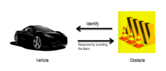
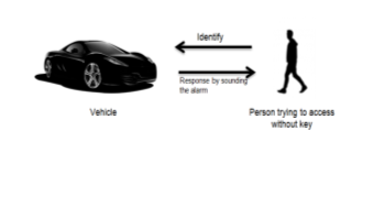
Figure 2. Obstacle and collision avoidance system
The proposed system consists of three sub systems which are a Motion detection system, System for rpm and speed calculation and voice enabled obstacle and collision avoidance system. The figure below shows the overall system design.
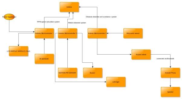
Figure 3. The overall system design
A system for calculating the RPM which would later lead to the speed of the vehicle was computed using Arduino and IR Sensors. The value which was produced was later produced on a LCD screen which in fact can be displayed to the driver by installing it in the cockpit. To setup such a system sensors and associated components like potentiometers and LCD display segments are required. The IR sensors once interfaced with the Arduino will produce the values which can also be displayed on the serial monitor of the Arduino IDE. RPM is essentially the number of times the shaft of a motor in a minute would rotate. In the case of a vehicle it would be the crankshaft of the engine. The system is designed as such when the input from the IR sensor changes from low to high it would then compute the time difference. Once the time required for one revolution is calculated this can essentially produce the rpm of the vehicle and finally the speed is computed. In practical application the IR sensor can be setup near the wheel of the vehicle.
To ensure the safety of the vehicle additional sensors are also included within the setup.And such a setup can create an anti-theft device. This include the motion detection PIR or the passive infra red sensor which when interfaced with arduino and connected to a led bulb and a buzzer would produce alert noises and glows warning lights once a person comes near the proximity of the sensor. The system would become activated when it would sense any kind of movement. This can be effectively be activated when the vehicle is parked in an unknown location or during the night time. To setup such a system many of the components would include the PIR sensor module, Arduino, Connecting wires, LED, Buzzer, Breadboard and 330 ohm resistors. Within the sensor a pyro electric crystal is present which would read the heat given out from a particular living being. The effect of the sensor is amplified by using component like Fresnel lens which is mounted on the system. There are two different potentiometers which are present on the sensor which would help to regulate the sensitivity and the trigger of the sensor. The module can essentially work in two different modes which are the H and the I modes. The H mode is powered by a 3.3 V power supply and it would go high when a person is detected within the range and after a certain period of time the output would go low. While within the I mode the output would go high as long as the person is in the range and it would remain as such as long as the person is in the range of the sensor.
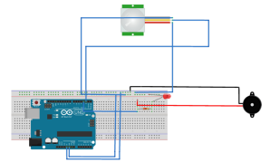
Figure 4. Blueprint of anti theft motion detection system
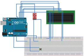
Figure 5. Blueprint of the rpm-speed calculation system
The Figures shown below shows the completely implemented circuit of the rpm-speedometer calculation system and anti-theft motion detection system
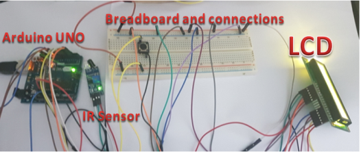
Figure 6. Completed circuit of rpm-speed computi ng system
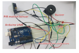
Figure 7. Completed circuit of PIR motion anti-theft system
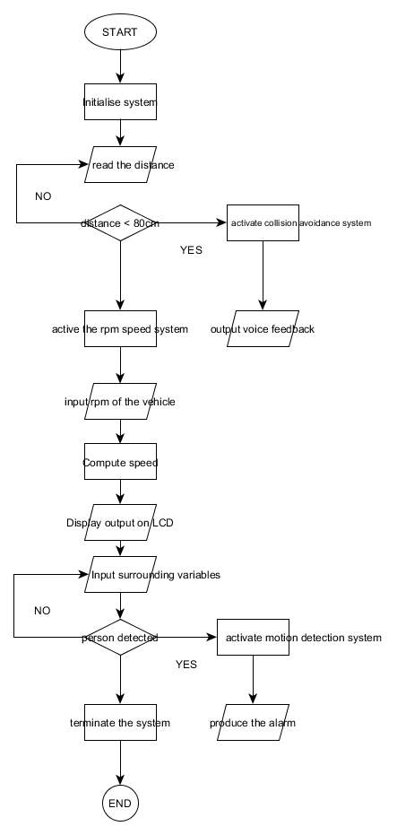
Figure 8. The overall system operation flowchart
- RESULTS AND ANALYSIS
The device was well assembled and all of the integrated sensors did respond ably to the regular tests that were carried out. The motion detection alarm system worked satisfactorily well and it was able to identify the obejcts accurately. Whenever a person approached near the sensor an alarm was triggered with warning LED lights in response to this event. The speedometer was exceptionallt functional in computing the rpm and the speed. The speed limit was set, the device was able to give out the warning signals and display it to the driver which was attached at the drivers cockpit. Once this was setup the driver was alereted about overspeeding and thus was able to fend off any kind of violations that might happen when tested in a freeway. In aditton to this to provide further safety to the vehicle, the distance sensor was able to detect the nearby obstacleswithin the range specified and then produce alarm signals using the buzzer alerting the driver about the event. This was repeatedly tested by keeping artificial objects nearby the vehicle. The results of the various tests that were carried out is shown in the figures and the tables below.
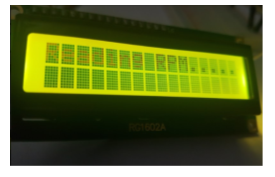
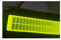
Figure 10. LCD displaying speed to the user
Figure 9. LCD displaying message reading RPM
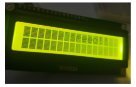
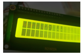
Figure 12. Warning signal displayed by the LCD
Figure 11. Reduce speed warning signal being displayed
yy
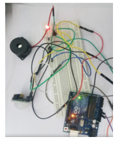
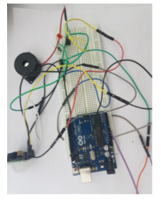
Figure 14. The PIR motion anti theft motion detection system after activating, the LED is seen glowing giving out the warning signal
Figure 13. The PIR anti-theft motion detection system before activating
Table 1. The results for rpm-speedometer
|
Trial number |
Speed limit (km/h) |
Speed (km/h) |
LED output |
|
1 |
20 |
11 |
Speed |
|
2 |
20 |
22 |
Warning signal |
|
3 |
20 |
30 |
Warning singal |
Table 2. The results for motion detection anti-theft system
|
Trial number |
Object nearby |
Sensor status |
Alarm status |
|
1 |
No |
Off |
Off |
|
2 |
Yes |
Off |
Off |
|
3 4 |
No Yes |
On On |
Off On |
- CONCLUSION
The device that’s developed is optimal in the road in any instance, and this system consisting of many associated sensors and the microcontroller can serve as a reliable and secure safety system for any vehicle. It will be very conveneient for people living in the city as heavy traffic is quite common event in daily life. To avoid collisions of any sort, to protect the vehicle from theft, and to control the speed under the limit and to eventually experience a safe travel avoiding any collisions which might lead to accidents this would be best ideal alternative for any driver.
In future work, many more sensors can be added to this system such as accelerometer, drowsiness sensor, Tire pressure sensor, object detection camera, which can additionally upgrade the protection features making it a exemplary safety gadget.
REFERENCES
[1] T. Wollinger and M. Wolf, “State of the Art : Embedding Security in Vehicles,” vol. 2007, 2007.
[2] Y. Elhillali, A. Rivenq, C. Tatkeu, J. M. Rouvaen, and J. P. Ghys, “Embedded Localization and Communication System Designed for Intelligent Embedded Localization and Communication System,” no. July 2014, 2007.
[3] S. Bouaziz, P. Lombardi, R. Reynaud, and G. S. Seetharaman, “Embedded Systems for Intelligent Vehicles,” vol. 2007, 2007.
[4] J. Yu and B. M. Wilamowski, “Recent Advances in In-vehicle embedded systems,” pp. 4623–4625.
[5] E. C. Guevarra, M. Ivan, R. Camama, and G. V. Cruzado, “Development of Guiding Cane with Voice Notification for Visually Impaired individuals,” vol. 8, no. 1, pp. 104–112, 2018.
[6] F. Corno, T. Montanaro, C. Migliore, and P. Castrogiovanni, “SmartBike : an IoT Crowd Sensing Platform for Monitoring City Air Pollution,” vol. 7, no. 6, pp. 3602– 3612, 2017.
[7] Y. Chen, Y. Tut, C. Chiul, and Y. Chen, “An Embedded System for Vehicle Surrounding Monitoring,” pp. 92–95, 2009.
[8] X. Lin, R. Lu, C. Zhang, H. Zhu, and P. Ho, “Security in Vehicular Ad Hoc Networks,” no. April, 2008.
[9] Z. Liu, “Vehicle Anti-theft Tracking System Based on Internet of Things,” pp. 48–52, 2013.
[10] H. Nicanfar, P. Talebifard, and S. Hosseininezhad, “Security and Privacy of Electric Vehicles in the Smart Grid Context : Problem and Solution,” pp. 45–53.
[11] J. Sun, C. Zhang, Y. Zhang, and Y. Fang, “An Identity-Based Security System for User Privacy in Vehicular Ad Hoc Networks,” vol. 21, no. 9, pp. 1227–1239, 2010.
[12] J. Wu, C. Kung, J. Rao, P. Wang, and C. Lin, “Design of an In-Vehicle Anti-Theft Component,” 2008.
[13] V. Goud and V. Padmaja, “Vehicle Accident Automatic Detection and Remote Alarm Device,” vol. 1, no. 2, pp. 49–54, 2012.
[14] P. E. An and C. J. Harris, “An Intelligent Driver Warning System for Vehicle Collision Avoidance,” vol. 26, no. 2, 1996.
Cite This Work
To export a reference to this article please select a referencing stye below:
Related Services
View all


DMCA / Removal Request
If you are the original writer of this essay and no longer wish to have your work published on UKEssays.com then please click the following link to email our support team:
Request essay removal