Non Linear Behavior of Elbows and Straight Pipes Under Pressure, Thermal Cycles and Bending Loading
| ✅ Paper Type: Free Essay | ✅ Subject: Engineering |
| ✅ Wordcount: 6793 words | ✅ Published: 18 May 2020 |
ABSTRACT
The high pressure pipeline is one of the most important components which are to be considered while designing a nuclear power plant. The American Society of Mechanical Engineers (ASME) codes lay the design guidelines of high pressure piping system. This paper provides a review of the technical reports, and investigations and research into the structural assessment of piping components such as pipe bends and elbows. This in a way can create a nearly complete picture of the piping components and its analysis. With the help of Finite Element Method, analysis of piping components has gained wide acceptance. Structural assessment studies have been conducted on the piping components which includes experimental, ANSYS software and numerical approaches. The existing capacity of literature for pipe bends is fewer and less explored in difficult circumstances, such as high temperature, pressure, torsional loading, and combined loadings. The major issues concerned with pipe bend are discontinuous stresses and cross-section ovalisation and thining.
Keywords: Elbows; Loadings; Stress; Finite element analysis; Non-linearity
Introduction
The majority of industrial setup at present involves large pipelines and piping networks. Refineries, petroleum rigs and power plants are some of the areas that integrate large piping system as a part of their infrastructure [1]. In nuclear power plants, highest importance is given to safety and reliability of piping arrangement. The failure in piping system of a power plant due to insufficient circulation of coolant raises the possibility of radioactive discharge to the atmosphere and severe harmful effects. Usually, piping networks in nuclear power plant can accommodate regular process loads (pressure and temperature) as well as cyclic loads such as in case of an earthquake.

Pipe bends or elbows may be introduced along with the straight pipes in the piping system in order to alter the direction of the pipeline and to provide flexibility to the pipe designing [2]. Elbows or pipe bends, more readily ovalizes in to a non-circular configuration (shell) under the influence of thermal expansion and other induced loadings than does the straight pipes (so called beams). So, pipe bends offer greater flexibility and thus, can tolerate larger strains [3].
These pipe bends are under complex loads of internal pressure, bending moment, torsion and their combinations caused by heat expansion [4]. Pipe bends relieves the energy of the system through local deformation [5]. Mourad and Younan have utilized pipe bends to bring flexibility to the overall piping system. Pipe bends have been reported to offer 5-20 times greater flexibility than that of a straight pipe with same material property and size [6].
When the pipe bend is subjected to a bending load, deformation induced in the cross section of the bend may work towards enhancing or reducing its strength (or stiffness) depending on the direction of applied moment. Even under a pure bending moment, complex interfacing is said to exist between the more flexible pipe bend and stiffer straight pipe creating a gradient of bending strain around the circumference and through the wall thickness. Behaviour of pipe bends under operational loads is explained assuming an elastic-perfectly plastic conduct. The elastic-plastic behaviour of pipe bend subjected to in-plane bending mode was first studied by Marcal using Finite Element Model [7].
Pipe Stress Analysis
Designing of piping entities fixed firmly to equipment such as turbines and compressors is a challenging task concerning their temperature variations, vibrations, fatigue. Poorly designed piping system can lead to formation of damaging forces and moments adversely affecting the pipe support structure and connected equipment.
Classification of stress
Primary stress
Any stress developed by an enforced body to balance the external forces applied and moments is defined as primary stress. Dead weight (which remains constant over the time) and internal pressure are distinctive of such loads. Primary stresses are not self-limiting. And, the failure due to primary stresses can be overcome by simple strain hardening of the material only if primary stress goes beyond the yield strength of material covering the whole piping range. Again, thermal stresses cannot be deliberated as primary stress. They can be grouped under secondary or peak stress.
Secondary stress
Secondary stresses are formed by the constraints enforced on the allowed displacement of piping rendered to thermal loads or by movement of anchor points. Thermal and displacement stresses are pertinent to secondary stresses. Secondary stresses are self-limiting as these stresses are likely to be released on local yielding and slight distortions of the piping system.
Peak stress
Peak stresses are the maximum stresses in the concerned part and can cause fatigue failure. In contrast to secondary stresses, these stresses do not lead to major distortions in the piping.
Numerical analysis
The stress analysis in piping systems is usually carried out using Finite Element Analysis (FEA) software. This method is based on the theory of beam element taking in to account stress intensity and stress concentration factors. Piping stress analysis in accordance with international piping design codes is basically of three types covering linear, static and dynamic analysis.
Loads measured in pipe stress analysis
Limit load
Structural reliability of the pipe bends in the piping system is expected on account of its ‘Limit Load’. Limit load analysis decides the maximum load that a perfectly plastic pipe bend can tolerate. In the theoretical calculations of limit load i.e., based on theory of small deformation, the effect of strain hardening in the material is not taken into account. It is assumed to be independent of loading sequence.
Limit load can be divided into instability loads or collapse loads depending on the effects of plastic failure on the material and can be assessed from the load-deflection or load strain curves. Instability load is indicated by the maximum load point in the monotonic load-deformation curve. The plastic instability load characterizing significant deformation taking place in the elbow without considerable increase in the load applied. It is depicted by a horizontal tangent in the moment end rotation curve, [8].
The plastic instability load is a function of yield strength of the material that results from instability in the shape of the structure. The term plastic collapse load defines the phase of significant plastic deformation. It depends on the sequence of loading resulting to the final collapse and may rely on large deformation theory and/or strain hardening theory. The three most common methods to calculate the plastic collapse load are: tangent intersection method (TIM), twice elastic deflection (TED) and twice elastic slope (TES). Twice Elastic Slope (TES) criterion being the most preferred method as suggested by ASME [9]. Graphical representation of the plastic collapse moment analysis criteria is shown in Figure 1. In general, a straight line is drawn passing through the origin of load (ordinate) v/s deformation (abscissa) plot. Straight line has a slope which is twofold as that of the line of initial elastic response. It can be expressed as tan ϕ1 =2 tan ϕ. The plastic load Pϕ can be found out by the intersection of the two curves. Han et al evaluated experimental plastic collapse loads of 90° elbows using the closed form solutions.
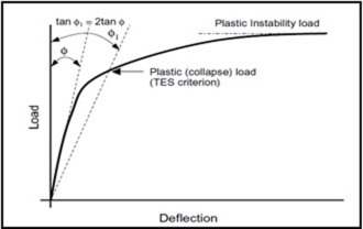
Figure 1: Definitions of limit load
The statements of plastic collapse load made from ASME code, The Ductile Fracture Handbook of Zahoor and by Chattopadhyay and coworkers, and by YJ Kim and coworkers were compared. The results of comparison brought about a conservative nature of ASME code solution, which may vary according to the nature of loading. The solutions made by Kim and coworkers were the least conservative of all. However, they delivered few non-conservative validations of some data [10]. The effect of bend angle on plastic limit loads under different loadings was recently evaluated using a 3-D non-linear finite element analysis. Characteristics of deformation, stress and strain were also discussed in detail. Bend angle was found to influence the limit load both at 0°=120° range under internal pressure, torsion moment and in-plane bending moment and at 0°=90° under out-of-plane moment. The proposed unified load solution was found to be in good agreement with finite element results [11].
Factors affecting the limit load
- Bending moment
Earlier researches have put forward limit bending moment of a pipe bend, to be a function of bending characteristics λ (dimensionless quantity) only. Spence proposed analytical solution for limit bending moment subjected to pure (in-plane) bending moment as (Equation 1):
(1)
denotes the limit load for straight pipe having same dimension as the pipe bend and
is the relative limit bending moment of the pipe bend [12].
Elbow is markedly more flexible than the corresponding straight pipe. In the absence of internal pressure, the flexibility of elbow/pipe bend is more and on increasing the internal pressure flexibility is reduced. It has grabbed increasing attention that the maximum circumferential stress is higher than the maximum longitudinal stress. Moreover, the maximum longitudinal stress is noticeably greater than the maximum stress of a straight pipe with the same cross-section, and does not take place at the top or the bottom of the cross-section. Cross-sectional ovalization is thought to be the main cause of such a behavior. There is significant difference between the proposed equation and the test results as the actual processing in a pipe bend is relatively a complex combination of bending moment and internal fluid pressure [13].
A superior energy formulation interconnects longitudinal strain energy due to bending, with hoop strain energy due to ovalization together with the effects of internal pressure. Consecutive coalescing of internal pressure and in-plane bending moment to the model is in a way such that internal pressure is kept at a constant value first and then the bending moment is increased monotonically in the second step. The reason for such an activity is that internal pressure usually does not increase all through the operation whereas; bending moment may increase considerably in accidental circumstances.
The core inference of the researches by Kramanos et al. is that the elbow response is directly correlated to cross-sectional ovalization, represented in Figure 2. For in-plane bending, the elbow flattens in to an oval shape which is symmetric relating to the plane of bending for closing or opening moment. In closing bending moments, excessive ovalization takes place with cross sectional flattening perpendicular to the plane of bending. The failure mechanism involves excessive flattening and increased strains at the “flank” of the central elbow cross-section. On the other hand, the flattening mechanism in opening moments is reverse to the one that takes place in closing moments; it is referred to as “reverse ovalization” and this reverse ovalization increases cross sectional height directing to higher bending moment capacity. So, in-plane opening moment flattens the pipe cross-section in the direction of the bending plane and failure arises of local buckling at the central cross-section of the elbow, at a site in the middle of the flank and the extrados [14].

Figure 2: schematic representation of ovalisation in (a) in plane closing moment (b) in plane opening moment (reverse ovalisation) [14]
Finite Element Analysis (FEA) technique has been thought of as a useful tool for understanding the behaviour of thin elbows under in-plane loading. Two in-plane closing mode bending tests and one in plane opening mode bending tests were carried to study the detailed mechanism of failure. The behaviour of elbow subjected to above processes was simulated with the help of ANSYS SHELL 181 and ABAQUS ELBOW 31 elements. Results obtained using Finite Element Analysis was found to be dependent on welding conditions. Replication of strains using shell elements were substandard compared to simulation of load-displacement relationships. Simulation was found to be dependent on wall thicknesses and mesh density [15]. Ying Tan et al have used Finite Element Analysis simulation to predict the behaviour of elbows under out-of-plane bending. Apart from the FEA shell and elbow element models, two out-of-plane experiments were conducted. The FEA calculations supports load-displacement results from experimental measurements. Experimental studies also validated load- strain behaviour predicted using FEA. The ABAQUS elbow element have shown better prospects in comparison to ABAQUS or ANSYS shell elements [16].
- Pressure
TES (Twice Elastic Slope) plastic loads were identified for 90⁰ pipe bends under the influence of pressure and out of plane bending using non-linear finite element analysis. The existence of internal pressure was assumed to complicate the behavior of pipe bends [17]. Kim et al have revealed the effect of the ratio of yield strength to elastic modulus on twice elastic slope plastic loads. In case of in plane closing and out of plane bending moment, a decrease in TES plastic loads was observed with increase in elastic modulus. A reverse effect was observed with in-plane opening bending. Finite Element analysis results are relevant to circumferentially cracked elbows under in plane closing bending. However, those results are not effective for circumferentially cracked elbows under in plane opening bending [18].
- Combined internal pressure and bending loading
Various methods have been evaluated over the decades for calculating limit loads for pipe bends under the complex loads of bending moment and pressure. Researchers have accounted theoretical, analytical and experimental methods for the failure in the pipe bends. The increase in the limit load of the pressurised elbows with increasing wall thickness and bend radius was validated by Duan et al. using experimental measurements [19]. The plastic collapse behaviour of pipe bend subjected to combined internal pressure and in-plane closing moment was considered in depth by Robertson et al. using elastic-plastic Finite Element Analysis (FEA). To identify the effect of loading sequence on the plastic collapse load, three loading patterns proportional loading, sequential pressure– moment (P-M) loading and sequential moment–pressure (M-P) loading were considered. The pressure only and bending only loadings were also considered for these three configurations. Piping structure once subjected to pressure-only loading was found to fail with initial yield developing in the centre of the bend at the intrados and then the plastic region was found to spread over the whole bend towards the junction with increase in pressure. Limit pressure lying adjacent to plastic instability pressure (large deformation collapse load) indicated insignificant effect of large deformation theory in pressure-only loading. However, in bending-only loading a distinct plastic failure mechanism was evident. Yielding is introduced in the middle of the bend at the crown and, as the load is increased, the plastic area extends both axially along the crown and circumferentially outwards, towards the extrados and the intrados. As such the plastic deformation materializes in the entire bend ahead of failure. Further, the limit and plastic instability loads are poles apart. In collective loadings of pressure and bending, P–M and proportional load configurations present failure surfaces complementary to plastic instability. In high pressure ranges, geometric strengthening is ought to take place. However, TIS method presented evidently different plastic load failure surfaces. This report published that the calculated plastic load depends on the failure mechanism instead of the state of collapse [20].
To incorporate the effect of both geometrical (ovality of the cross section) and material non-linearity (wall thickness), a comparison of the collapse behaviour of pipe bends having elliptical and semi-oval cross sections under the influence of in-plane closing bending moment was made. The thinning effect was minuscule for both elliptic and semi oval cross sections of the pipe bend. The disparity between reference models and models with elliptic and semi-oval cross sections was found to increase with the increase in ovality. A closed-form solution (Equation 2) was put forward, using regression analysis in Datafit package (Datafit, 2009), to include the effect of ovality in the calculation of collapse load of the pipe bends [21].
(2)
Non-linear Analysis
A serious drawback with the theoretical explanations is that they are resulting from the elastic analysis concepts, and cannot be used for the non-linear analysis. In accidental situations, plasticity behaviour dominates and elastic analysis cannot analyse the response of a pipe bend precisely. Kramanos et al. reported the analysis of elbows with nonlinear elastic-plastic shell finite elements, and results were verified by experimental measurements. Again, substantial efforts to calculate ultimate moment capacity focused on the in plane bending moments and not much attention are directed to out of plane bending. However, this work was engaged in finding the ultimate capacity of 90 deg pressurized steel elbows subjected to in-plane or out-of-plane bending. This benchmark study explains the geometrical nonlinearities and inelastic behaviour emerging in the elbow considering large-strain plasticity model. The effects of internal pressure (40% of the entire plastic pressure) on the ultimate moment capacity of elbows have also been investigated at length. The cross section of the elbow was found to undergo flattening ovalization represented by a four-hinge plastic mechanism under in plane closing moments. The internal pressure serves to diminish the cross sectional ovalization and supports the ultimate moment capacity, as well as the curvature. In in-plane opening moments, the diameter on the plane of bending and moment of inertia increases pertinent to “Negative” ovalization. The ultimate opening moment of unpressurised elbow is found to be much higher than the equivalent ultimate closing moment. Under opening moments, inelastic buckling leads to failure.
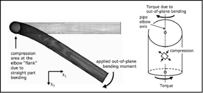
Figure 3: (a) Deformation of a 90 deg elbow under out-of-plane bending. Note the deformation of the straight pipe portion. (b) Schematic representation of the state of stress on an arbitrary location at the “intrados” of the curved pipe portion due to out of-plane torque [22].
Cross-sectional ovalization is evident in case of out-of-plane bending at 45 deg to the pipe axis (see Figure 3 (a). In elbows with zero pressure, failure mechanism involves buckling at the flat part of the ovalized elbow. The obliqueness of the buckle relating to the pipe axis is because of a coupling of torsional and bending load stress (Figure 3 b). On comparing the three bending moments i.e., out-of-plane bending, in-plane closing bending and in-plane opening bending, the ultimate moment capacity follows the order:
In-plane opening bending>out-of-plane bending> in-plane closing bending
In pressurised elbows, the cross sectional ovalization is reduced, and the ultimate out-of plane bending moment is enhanced. So, buckling may affect the adjoining parts of straight pipe [22].
In addition to non-linear finite element analysis on straight pipes as well as elbows, Tan et al have validated the same with experimental studies. An successful progression in the correlation of test analysis is noticed on comparing the test data with FEA for straight pipes and elbows. Also, two four-point-bending tests were proposed on straight aluminum pipes and two stainless steel elbow tests were suggested under in-plane closing and in-plane opening mode bending. The FEA models and test results were found to be very much synchronized. This work affirmed that the comprehensive actions of straight pipe and elbow from non-linear finite element analyses match to the outcomes of physical tests [23].
Li et al. have performed three-dimensional non-linear finite element simulation analyses on pipe bends subjected to pure out-of-plane bending moment or combined internal pressure with out-of-plane bending moment. Limit load solutions of pipe bends were derived using small displacement analysis and large displacement analysis. The effect of varying internal pressure under combined loads of internal pressure and bending moment has also been discussed. The straight pipes of dimension L>3r and pipe bend angle of 90°is chosen so as to discard the end effects on limit loads. Under large displacement analysis, the effect of bending modes was prominent for thinner pipe bends subjected to pure out-of-plane bending moment. If large displacement analysis with higher limit loads are studied, normalized solutions f(PL/PoS, ML/Mo) were built upon the bending characteristics. However, no significant difference was observed among the different bending modes in small displacement analysis. A thorough insight on this study brought out that internal pressure does not led to stiffening effect on the limit bending moment according to small displacement analysis however, in view of large displacement analysis internal pressure does have a stiffening effect on limit bend moment. Such an effect is due to the reduction in the ovalization in large displacement analysis with the increase in internal pressure and a consequent enrichment of the ovalization on small strain assumption [24]. The crack like defects appearing as a result of continued cyclic loading during the operation and metal deterioration is known to have a detrimental effect on the limit load of the pipe bends. A study on shape imperfect pipe bends directed that critical throughwall circumferential crack deteriorates the collapse moment of the elbow. A thorough analysis of bend’s cross sectional ovality and thickness on the collapse moment of cracked pipe under in plane bending loading was carried out. Thickness variation in the cross section is immaterial to the collapse moment of pipe bends however, ovality exceeding 5% have considerable effect on the collapse moment [25].
Numerous studies of experimental and numerical analysis on the mechanical behavior of pipe bends for industrial piping applications are existent in literature. However, not much attention has been directed to study the structural behavior of elbows in buried pipelines considering their interaction with the surrounding soil. Recently, Vazouras et al. have reported the use of pipeline elbows as ‘‘mitigating devices’’, if placed at optimum distance on fault crossings, reducing ground-induced action. If elbows are placed too close to the fault zone, then reverse effect causing either local buckling or elbow tensile strain failure is observed, reducing pipeline capacity against fault shift. Figure 4 summarizes the results for three bend angles when used at a distance Le = 45 m from the fault. Local buckling is denoted by LB, tensile failure at the bend area by TL-E and tensile failure near the fault as TL [26].

Figure 4: Fault displacement corresponding to first limit state of the pipeline for different values of the bend angle (Le = 45 m; β = 25˚; Clay I soil) [26]
Shakedown load
Stress analysis of piping accommodates the static and dynamic parameters. Static parameters include pressure, thermal expansion, constant load bearing and endpoint displacement, which have already been discussed in the preceding sections. Dynamic parameter comprises of accidental loading, and seismic loading, latter is further categorised in to operation basis earthquake (OBE) and safe shutdown earthquake (SSE). The OBE is a design load, although SSE is reflected in some accidental situation. All of these efforts were directed towards monotonic loading of elbows. However, during a strong seismic event, the elbows experiences strong repeated cyclic structural loading, related to deformation of the steel material in the inelastic range. Under these conditions, the elbow may demonstrate a buildup of plastic strain (“cyclic creep” or “ratcheting”) resulting in ultimate failure. Well-ordered plastic deformations are assumed in pipe designing without comprising on the safety factors of the component. In the plastic region, for structures experiencing monotonic loading the limit load is identified and with cyclic loading shakedown limit load (SD) is realized. If applied load exceeds the limit load, structural failure is resulting of gross plastic deformation or plastic instability while ductile failure mechanisms (reversed plasticity or ratcheting) is evident if the applied load goes beyond the elastic SD limit. Elastic SD is the presence of the small phase of plasticity in the opening loading cycles followed by fully elastic behaviour. Reversed plasticity (plastic SD) failure relates to the plastic strain initiated in the structure under the loading cycle which can be reversed completely at the finish of the unloading process. Ultimately, structure failure results after a few cycles of loading and unloading due to low cycle fatigue. The other mode of failure i.e., ratcheting corresponds to the build-up of plastic strain through the loading-unloading cycle until ductility is exhausted leading to collapse of the structure. A diagram known as Bree diagram gives the generalized interaction (Figure 5).

Figure 5: Bree diagram of defect free components illustrating the safe and the unsafe operating domains
ASME Section VIII Div. II Design by Analysis (DBA) [27] classified the stress in the 1960s; the different stress limits are defined by certain codes which vary with process environment. Stresses are categorised in to primary, secondary, and peak stresses. These stress limits are primary to define the service life of any structure. The ASME code classified the stress limits as follows:
Primary stress can be normal or shear stress build up as a result of applied load. A significant feature of primary stress is that it is non self-limiting and, failure or deformation can occur if it surpasses the yield stress. Secondary stress builds up as a result of self-restrictions of the structure or limitations of different materials in the surrounding. So, secondary stress is self-limiting. Local yielding or minor distortions may lead to such stresses. However, mere application of secondary stress cannot result in a failure. Secondary stresses include the thermal stress or the bending stress at a gross structural discontinuity. Peak stress is due to the concentration of stress through local discontinuities. Although such stresses does not cause major distortion in the structure, but may initiate fatigue cracks and brittle fracture. A New method to compute B2 stress index of any piping components was adopted. Both experimental technique and Finite Element Analysis were used to find out the collapse moment of piping components. Non-linear Finite Element Analysis (ANSYS shell models and ABAQUS elbow models) was practised to realize two tests on straight pipes and eight tests on elbows subjected to various loading configurations such as in-plane closing, in-plane opening and out of plane bending. Nonlinear FEA with ANSYS SHELL 181 elements and ABAQUS ELBOW 31 were found to provide precise predictions of the behaviour of an elbow and straight pipes subjected to monotonic loading [28]. According to the ASME DBA [27] and Muscat et al. [29], plastic deformation may be caused by primary stresses alone or by association of secondary and primary stresses together; however, peak stress is well bounded and can only be expected in case of extensive cycle fatigue. Both primary together with secondary stresses had to be considered for calculating the SD limit. The design limit of DBA for this problem is 3Sm. Where, Sm stands for the permissible stress intensity of material and is calculated using the equation of ferritic steels:
(3)
Abdalla et al. [30] identified an easy practice to figure out the lower bound SD limit load without executing the usual iterative elastic solutions or time consuming elastic-plastic cyclic loading. Their problem solving technique involved the two bar model and Bree cylinder. The two steps involved in the process includes: first application of only cyclic loading below the yield stress i.e., elastic analysis (simulating unloading) and then Elastic-Plastic exercise that again involves two steps: first is the application of the monotonic static loading without exceeding the yield and the second is application of cyclic load monotonically beyond the yield stress keeping the applied static load at a constant value. The superposition rule is then applied to calculate the residual stress components:
(4)
: Von-Mises Equivalent residual stress
I: Load increment
: Elastic-plastic stress components
: Elastic stress components
: Applied moment increment
: Reference moment
Linear Matching Method (LMM) concept was designed by Haofeng et al. This method involves considering two cases, first of internal pressure and in-plane bending loads, second one involves internal pressure and temperature loads. An important criterion for designing the piping system is the temperature dependant yield stress. This model of Linear Matching Method is recognized to provide precise shakedown limit and limit load is in accordance with the one predicted via incremental full cyclic Finite Element Analysis and ABAQUS Rik’s analysis [31].

Figure 6: Thinning locations employed within the shakedown FE analyses of elbow half geometric models at (a) intrados (b) extrados (c) crown and elbow full geometric models at (d) intrados (e) extrados and (f) crowns [32].
A direct non-cyclic technique was arranged by Oda et al. to induce elastic shakedown domains in thin-walled 90° elbows. The elbows were all together subjected to steady internal pressures and cyclic in-plane and out-of-plane bending moments. Wall thinning was placed at the intrados, extrados, and crown one by one. Figure 6 shows thinning locations at the intrados, extrados, and crowns respectively of symmetric FE geometric models. Effects of thinning depth and thinning location under both cyclic in-plane and out of- plane bending modes were investigated. A comparison was made among the generated shakedown boundaries and that of sound elbows. Elbows subjected to out-of-plane bending moments were found to have comparatively higher shakedown domains than in-plane bending loading. The thinning at the intrados or crown was more effective in decreasing the elbows shakedown domains in both the bending modes [32]. Ratcheting tests were done on elbows using multiaxial testing machine. The greatest ratcheting strain arose in the hoop direction at the flanks. The ratcheting strain rate was found to increase with an increase in the level of bending loading at constant internal pressure [33]. The ratcheting behavior in 90⁰ elbows was predicted by Kulkarni et al. with the help of ANSYS using Chaboche model. Chaboche model was found to yield fairly accurate estimation of ratcheting in 90⁰ elbows [34].
Load bearing capacity of fractured structures
Shakedown analysis of fractured structures
A 3D analytical model of the piping system was put forward by Shiratori et al. for predicting the ratcheting, buckling and penetration behaviour of a surface crack initiated under seismic loading [35].

Figure 7: Crack penetration behavior in sound specimens (Nf = 87) [36].
Further, Takahashi et al. proposed three dimensional elastic-plastic analysis of carbon steel pipe elbow specimen to find out the area of crack penetration and direction of crack growth. Local wall thinning was introduced at extrados, crown and intrados zones of elbows and low cycle fatigue behaviour was considered without applying internal pressure under in-plane bending moment. The crack was found to propagate in the longitudinal direction in sound (Figure 7), extrados and crown specimen while, it propagates in hoop direction in the case of intrados (Figure 8) [36].

Figure 8: Crack penetration behavior in intrados specimens (Nf = 61) [36].
The conception of leak before break or LBB (replacing traditional concept of Double Ended Guillotine break (DEGB)) was brought about to predict the failure mechanism in the piping systems. To investigate the fatigue growth and leak before break behavior of elbows, three cyclic load experiments were conducted. Experimental results affirm to the assumptions made by LBB concept. Cracks propogated in a semi elliptical manner under cyclic loading however, a 10% deviation was noted between the values of experimental and numerical test result [37].
Limit load analysis of fractured pipe bends
Recently, a systematic study has been conducted on asymmetrical radial deformations together with local wall thinning in a pipe subjected to internal pressure loads. Radial displacements were calculated and verified with Finite Element Analysis study. A new method was proposed to find out the internal defect size in pipes under the action of internal pressure. The numerical results obtained using Finite Element studies were in good agreement with the analytical values obtained through the experiments. So, if radial displacements are identified, then defect size can be predicted using horizontal and vertical displacements [38].
A series of fracture tests were carried out on austenitic and ferritic pipes and elbows of different diameters and a comparison was completed with the theoretical values using plastic limit load and R6 approaches. For safety assessment of pipes within the signified dimensions and materials was done using the theory of plastic limit load. The limit load equations were preferred for circumferentially cracked elbows. The R6 approach was supposed to provide quite accurate prediction of crack initiation loads [39]. The combined effect of internal pressure and bending loads on the plastic collapse moments of a through-wall circumferentially cracked (TCC) elbow was considered in detail. Chattopadhyay and Tomar proposed a closed form equation for predicting the failure mechanism in through-wall circumferentially cracked elbows exposed to combined loads of internal pressure and in-plane closing or opening bending moments [40]. Another study reported the use of Finite Element Analysis to see the influence of internal pressure on the in-plane plastic collapse moment of Through Wall Axially Cracked (TAC) elbow [41]. Taking into account geometric nonlinearity of the structure, a thorough analysis of plastic collapse load for un-cracked and circumferential through-wall cracked pipe bends under the load of torsion moment was carried out. Three dimensional FE analysis brought out that in case of un-cracked pipe bends, plastic collapse load is largely distressed by radius-to-thickness ratio. However, in case of cracked pipe bends, the weakening factor was inversely related with crack length and three distinctive stages were evident as with that of bending [42].
A study conducted by Abid and Siddique employed three dimensional sequentially coupled non-linear transient thermomechanical testing to see the effect of tack weld positions and root gap on welding distortions and residual stresses in a pipe flange joint. The axial displacement and tilt of flange face was found to vary with tack weld location. However, Tack weld location is insignificant with respect to the overall residual stress distribution. Finite element analysis was also conducted on gasketted joint subjected to internal pressure and temperature loads. Their experiments revealed that the joint designed for pressure loads possibly fails when subjected to supplementary thermal loads and failure is attributed to flange yielding. [43].
Conclusion
Through this review, we wish to highlight structural assessment studies of piping components such as pipe bends and elbows. There is immense scope for further work on the effect of combined loading, and end effects on piping components. Literature for Limit, collapse and disintegrate loads analysis are not yet available over the whole range of bends. Constraints associated to piping component such as creep characteristic, optimization is least examined as far as pipe bends are concerned. Geometrical and material non-linearity is also not studied in detail in elbows and pipe bends. So, forthcoming researchers have whole lot of scope in this area to cement the gap between the proposed model and real time piping systems in future.
References
Cite This Work
To export a reference to this article please select a referencing stye below:
Related Services
View all


DMCA / Removal Request
If you are the original writer of this essay and no longer wish to have your work published on UKEssays.com then please click the following link to email our support team:
Request essay removal