Fly by Light in Aircraft Systems – Analysis
| ✅ Paper Type: Free Essay | ✅ Subject: Engineering |
| ✅ Wordcount: 4541 words | ✅ Published: 07 Aug 2017 |
Fibre optic cables are widely used in telecommunication and network. It is known for its properties which is lighter than standard copper wire, able to carry multiple signals in single cable, no electrical current involved in the cable, cheaper than copper cable because it is made from silica (glass), and does not
List of abbreviations
- FBW- Fly-by-Wire
- FBL- Fly-by-Light
1.1 OVERVIEW
At the early stage of aviation, aircraft utilized cables and pulleys for controls also known as mechanical linkage. This cables and pulleys act as pull and push system to move the flight control’s surfaces at the expense of the pilot’s effort. By using the cables and pulleys, every forces act on the flight control surfaces are being transmitted to the cockpit control and felt directly by the pilots which they have to counter these forces using their own strength without any assistance. Early aircraft were lightweight and the aircraft can only fly at a slower speed thus aerodynamic force is not strong making it possible to manoeuvres the aircraft.
With new emerging technology and war at that time, air superiority has become an advantage. Aircraft needs to fly faster, carry more payload and strong. This is when hydraulic systems plays an important role in aircraft control system. By using hydraulic systems, aircraft can fly faster due to the pilot does not have to put extra effort to move the control surfaces with increasing aerodynamic forces. Hydro-mechanical control system is a system which mechanical linkages are connected to the hydraulic system. This system utilized cables, pulleys, and gears at the cockpit control and hydraulic system consist of pipes, reservoir, valves and pumps at the control surfaces. With hydro-mechanical system, the aerodynamic forces acting on the control surfaces are not felt by the pilots making it easy to controls. Stick shaker and artificial feedback are the methods to replicate the aerodynamic forces acting on the control surfaces to the cockpit control. It was to ensure that the pilot does not manoeuvre the aircraft beyond its limitation.
Although the hydro-mechanical system gives a plenty advantages to the pilot, it was deemed as heavy, hard to maintain and not practical for larger aircraft as the cables would have to run over a long distance of aircraft fuselage.
Commercial aircraft nowadays are bigger, faster and fly higher than before. Hydro-mechanical control system might not able to accommodate the complicated and sensitive controls made for passenger’s comfort. Nowadays, majority commercial airliners use Fly-by-Wire system. FBW system replaces the cables, pulleys and gears with copper wires which carries electrical signals from the cockpit control to the control surfaces. FBW eliminate the needs to maintain the cables, pulleys or the gears thus reducing weight of the aircraft. FBW is very efficient due to it being electronically control by computers which manage the autopilot system and aircraft system.

Although FBW is considered as the best option available today, it is still needs to be upgrade. Copper wire can only carry one signal for each wire which means for a single system that might needs four signals, it needs four copper wires. Due to this nature, typical aircraft with FBW will have a bundles of copper wires and for maintenance side, working with bundles of wires takes time and lot of manpower. FBW system is still considered to be heavy due to the amount of copper cables involved and caging due to susceptible to electromagnetic frequency.
Fly-by-Light is a technology that might be the answer for future aircraft development. FBL technology is not a new thing but the research is slowly progress as it still being tested and research since the 90’s. Although FBL might not be implemented in near future but the concept have been use in today’s inflight entertainment system which utilized fibre optic cable to cater all passenger’s preference.
1.2 IMPORTANCE OF THIS STUDY
In the world of aviation, safety comes first, revenue comes second and followed by everything else. The information gather in this study might prove that FBL has potential for future aircraft development. Aircraft manufacturers and aviation operators such as airline companies and private sectors always be look into more reliable aircraft, weight-fuel saving and easy to maintain. This study will prove whether it is possible or not to replace the old fly-by-wire system with new fly-by-light system and offer more advantages.
1.3 AIM AND OBJECTIVES
The aim for this study is to investigate whether fly-by-light is the future for aircraft system and how it will affect the traditional maintenance practice. In order to complete this study and to achieve the aim as stated, few objectives must be completed such as:
- To discuss the advantages and disadvantages of using fibre optic cables over standard copper wire on commercial aircraft and military aircraft.
- To discuss the development and potential of fly-by-light on aircraft system.
- To show the complication of using fly-by-light system on commercial and military aircraft.
- To find out whether it will be more cost effective for aircraft manufacturers to manufacture new aircraft system in future aircraft development.
- To find out the cost and its effect on traditional maintenance practice.
1.4 HYPOTHESIS
Technology advancement always research for a new alternative to make aircraft lighter, lower cost and increase reliability. Fly-by-wire system manage to make modern airliners bigger, fly higher, more reliable, save cost and increase in revenue. If fly-by-light system is going to replace the FBW system in the future, commercial and military aircraft will see a lot of improvement in terms of fuel saving due to weight reduction, faster response rate and more simple system installed that is easy to manufacture and maintain. Fly-by-light may not be the system in near future due to the nature of fibre optic technology that is not suffice to withstand aircraft environment but with improvement and further research into fibre optic technology, Fly-by-light soon will replace the fly-by-wire system.
1.5 LIMITATION
The main purpose of this study is to do a research whether fly-by-light system might replace the fly-by-wire system in the future. It does not discuss about implementation or direct costing which may involve specific value because this system is yet still under research and development. Any costing stated in this study is mainly an estimation based on current market value.
2.1 Overview
Today’s aircraft have shown a significant improvement in flight control system. Boeing 787 and Airbus 380 have successfully flown on a fully fly-by-wire system independently. Having the flight control system runs solely on electrical power, the respective aircraft have managed to change every aspects that are common to previous aircraft. Boeing 787 and Airbus 380 are using no-bleed engine as the flight control system now run on electricity, the actuators hydraulics are being pumped by electrical pump and air-conditioning are also run on electrical power. This technological advancement have yet to have its downside which is the aircraft require a lot of shielding in order to protect the electrical system from electromagnetic interference or EMI. The shielding to keep the EMI at minimum have its own disadvantage because shielding is heavy and it makes it hard to access during maintenance. It might be a success for fly-by-wire system in Boeing 787 and Airbus 380 but by understanding of what FBL can offer for further aircraft development is very promising.
2.2 FLY-BY-LIGHT AS NEW EMERGING TECHNOLOGY FOR AIRCRAFT SYSTEM
2.2.1 Advantages of using fibre optic cables over copper cables
Fibre optic cable is made up of bundle of glass strands coated in insulated cover. Fibre optic cables nowadays widely used for networking and communication as it offers many advantages over copper cables. According to Collins (2015) here is the advantages of using fibre optic cables:
- BANDWIDTH
Fibre optic offers high bandwidth compared to copper wire. High bandwidth means that fibre optic cables are capable of carrying multiple signal over one cable instead of one signal over one wire with copper wire. Aircraft system sends multiple signals for one flight control and using conventional copper wire in FBW system, it needs a bundle of wires just for one flight control. Using fibre optic cable to replace copper wire will reduce significantly the amount of copper wire thus reducing the weight of the aircraft.
- HIGH SPEED
By understanding the concept of fibre optic cable, it has a faster signal transfer rate compare to copper wire. Fibre optic cable carries light signal in which the speed of light travels much faster than electrical current in copper wire.
- DISTANCE
Fibre optic cable capable of carrying signal on longer distance without degrading the quality of the signal as the light have less susceptibility to signal lost during transmission. It does not require any step up or step down voltage like copper wire does.
- SECURITY
Copper wire are easily tap into and less secure compared to fibre optic cable. Electrical signal in a copper wire are also easy to be change by intercepting the signal and can be done by non-professional. Whereas fibre optic cable are made from glass strands which makes it incredibly difficult to intercept the signal without breaking the cable. Even with professionals, the cable are very challenging to intercept midway and if it were done at the source, it is still very tough to change the signal without the proper equipment.
- RELIABILITY
Copper wire and fibre optic cable both susceptibility to worn out over time but instead of posing a fire hazard like copper wire does, fibre optics does not pose any risk of fire hazard as it only carries light signals. Temperature, moisture and severe weather condition could cause copper wire having signal loss or even complete loss of connectivity but it does not happen with fibre optic cable. In terms of studier, fibre optic cable can withstand around 100-200 lbs. of pressure without damaging the cable while copper wire typically are delicate and enough to withstand only at about 25 lbs. of pressure before damaging the wire.
- CABLE SIZE
Higher amount of connections require more copper wire to be able to process all the signals at a higher speed as copper wire performance in signal transferring is directly connected with the cable size. Fibre optic cable size does not determine by the size of the cable and by that, it can be used for multiple signals transfer without affecting the speed or the quality of the signal. Fibre optic cable are much simpler to use and relatively lighter than copper wire.
- COST
Although fibre optic cable today are still considered as more expensive than copper wire in a short term but with it being lighter, more reliable, and much better performance than copper wire makes it a valuable investment for a long run. Fibre optic cable are also easy to maintain which in turn less cost needed.
- IMMUNE TO ELECTROMAGNETIC INTERFERENCE (EMI)
Copper wire carries electrical signal which runs through in bundles of wire in close proximity. When electrical signal flow through a wire, it creates an electromagnetic field. Electrical signal are easily affected by electromagnetic field which then deteriorate the signals. Not only had it affected by its own electromagnetic field, it is also affected by electromagnetic frequency given out by other electronic devices such as a hand phone, microwave, or even lightning strike. Using light signals by fibre optic cable, it does not create any electromagnetic field or affected by other electromagnetic frequency. Being immune to EMI, fibre optic cable does not require shielding as copper wire does. No shielding means an extra weight loss using fibre optic cable rather than copper wire.
2.2.2 INSTALLATION OF FIBER OPTIC CABLE ON AIRCRAFT
According to Garg, Linda and Chowdhury (2014), FBL system will follows the same concept as the FBW system except for FBL, the sensors will be replaced with optical rather than standard electrical or electronic as on FBW system. All the cables routing will be no different than copper wire in FBW but with added advantage of using less amount of fibre optic cable because it is capable of transmitting more than one signal per cable making it lightweight and its immune to EMI needs no shielding thus reducing weight even further.
In order to change all the sensors and actuators into optical, Photonic Controlled Actuation System or PCAS is introduced. This actuator system is a modified version of standard Electro Mechanical Actuator or EMA but with added optical controller that commands EMA. The signal that being sent to EMA is the same signal sent by the flight control computer. In order for the EMA to received and react to the signal, the engineers have modified the EMA to make sure the signal sent via light from the optical controller is readable. As the PCAS will utilized light signal to react, all other sensors such as the actuator position, motor position and current are replaced by optical sensors.
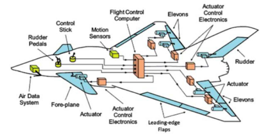
Figure 1: Fly-by-Wire standard wire routing in aircraft (ICCCI, 2014)
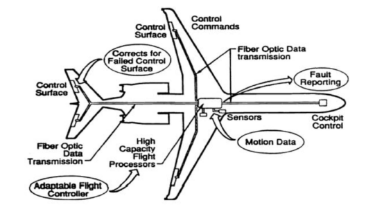
Figure 2: FBL utilized the same cable routing as the FBW but with reduced cable amount (ICCCI, 2014)
2.2.2 FLASH PROGRAM FOR RESEARCH AND DEVELOPMENT
Based on John R Todd (1996), during the mid-1994, McDonnell Douglas team start working for two years project called the Fly-by-Light Advanced System Hardware Program or also known as FLASH Program. FLASH program was initiated to develop a reliable and cost effective FBL system and hardware for aircraft in military and commercial. This FLASH program aims to be able to demonstrate the FBL system use on aircraft specifically. In summer 1996, the team was able to put on two demonstration of aircraft using FBL system. Ground demonstration with the FBL system on a partial flight control system and during flight demonstration, aileron trim control system was replaced with FBL system. The FBL system that was installed on the test aircraft was built on open architecture platform which have its own advantage.
2.2.2.1 OPEN ARCHITECTURE CONCEPT
In the computer industry according to Computerhope.com (2017) the definition of “open architecture” is an open platform and was built on common platform so that any hardware and software can be use, reconfigure or modified to fit the platform such as the IBM computer. In aviation, Flexible Vehicle Management System or flexible VMS is the same as “open architecture” used in computer industry. Flexible VMS means that the aircraft system will be built on base platform using common hardware and software which can be expanded, outsourced and reconfigured to fit any aircraft system platform be it in commercial or military configuration. The benefit of having open architecture in flexible VMS will encourage more development on a system and more integration of new role with potential growth. Other benefit from using an open platform in flexible VMS is it will reduce cost significantly as the platform will use a very identical and same modular blocks so there is no need for further research for new platform every time new idea and innovation present itself. Future aircraft system such as the FBL system can be built on open architecture which not only save cost for development but also time.
By using open architecture concept on flexible VMS, the McDonnell Douglas Aircraft Control and Avionics System or ACAS has managed to expand and contracted a single platform to fit new FBL system according to the need of transport aircraft with various size and shape. Using the flexible VMS for ACAS has managed to maximize the commonness and the ability to share hardware on any platform regardless of the commercial aircraft or the military aircraft while keeping the development cost down and save time. The ACAS architecture is also part of the FLASH program to develop and built sustainable and reliable FBL system in future aircraft system.
2.2.2.2 MAJOR ASPECTS IN FLASH PROGRAM
As stated by John R. Todd (1996), FLASH program consist of two major aspects that is needed to achieve. The first major aspects of FLASH program responsibility is to develop integrated fibre optic cable plants and every components needed to make it work. The first development focuses on producing reliable cable plants and its components and also to figure out the installations procedure as well as the maintainability of the new system components. The cables and components must be able to withstand aircraft environment to fit the purpose. This aspect of development has been assigned as TASK 1A. Major associate with MDA-TA for TASK 1A in the FLASH program was Berg Electronics.
TASK 2A is the advancement from TASK 1A development where the cable plants and components that were developed and produced in TASK 1A were used to demonstrate FBL system on flexible VMS. Honeywell as the major team mate along with HR Textron, GEC-Marconi and Allied Signal were involved in the development of TASK 2A as the effort of develop and implement the new FBL system on aircraft. The team have managed to produce and develop the main flight control fibre optic data bus system, Fly-by-Light primary flight control computers (PFCs), a representative remote terminal/ distribution unit (RDU) which is a smart actuator with low cost fibre optic data links to the RDU and lastly, a flight test done on the FBL aileron trim system.
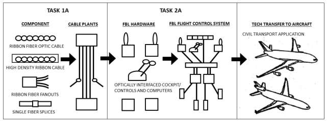
Figure: TASK 1A and TASK 2A in FLASH Program
FLASH Task 1A successfully developed high density fiber optic ribbon cable and connectors that passed the aircraft environment test and deemed as flightworthy. This ribbon cables and connectors will be the backbone of the FBL system for aircraft control system. Single-fiber fanout assembly, conduit systems including clamps, splitters and connector backshells were also developed by Task 1A for FLASH program. MDA – Advanced System & Technology also responsible in developing a safe and reliable installation procedure as well as maintenance procedure that are cost effective for both manufacturer and clients. Increased reliability and maintainability also ensure a reduction cost in installation and maintenance labour.
AVMAC was the high density fiber optic connector being developed by Task 1A under the FLASH program that was meant to be the termination of fiber optic ribbon cable. The ribbon cable is basically constructed using 18 fibers arranged into linear arrangement into one ribbon. The advantage of having the fiber optic ribbon cable for FBL system is that the ribbon cable can provide several optical fiber in one small integrated package apart from bundles of copper wires as in FBW system. Although the fiber optic ribbon cable consist of 18 optical fibers, the physical aspect and appearances of the ribbon cable is not far from a single channel fiber optic cable. The ribbon cables are also has been classified as flight qualified by MDA – AS&T which met all the aircraft environment specifications, mechanical requirements and optical requirements set forth by MDC specifications. The ribbon cable is not develop only for 18 optical fibers installation but it can be reduce or increase according to the requirement but Task 1A team considered 18 optical fibers is the best option and suitable for FBL system on aircraft.
Identical to fiber optic ribbon cable assembly is the optical fan-out assembly. The difference between these two cable is one of them carries all 18 optical fibers in one protective casing and the other one converts the package into 18 individual fiber optic channel. Fan-out assembly designs and material use is the same as the ribbon cable assembly but fan-out assembly use to separate 18 optical fibers into single channel so that each single optical fiber channel can be routed to several locations on aircraft.
During FLASH task 1A, the team encountered many challenges to ensure the reliability of the installation and maintenance for fiber optic cable. One of the option they selected was using a tube to house the fiber optic cable. This tube is a conduit that is made up of clear plastic tubing. The conduit is the best option to safe guard the fiber optic cable since it is also lightweight and with the added benefit of it being easy to replace, remove or add fiber optic cable with ease. Maintenance wise, this clear plastic conduit is relatively transparent makes it easy to detect any damaged fiber optic cable using a laser fault finder. The team also develop a special connector which is the backshell or the conduit adapter to ensure the conduit is easy to access and protect the fiber optic cable.
Task 2A for FLASH program is to develop and installation of the flight control using FBL system using parts and components produced by Task 1A. Task 2A will be responsible to put on FBL system onto test aircraft but limited to certain flight control surfaces for ground and flight demonstration.
Ground demonstration team for Task 2A have managed to develop and installed the main flight control fiber optic data bus system, the FBL primary flight control computers or the PFCs, a remote terminal/ distribution unti or the RDU and a smart actuator along with an affordable fiber optic data link to the RDU.
The demonstration from ground team for Task 2A will validate whether the aircraft closed loop system with FBL installation will function accordingly. The ground demonstration covers all ACAS architecture including: Active Hand Controllers (AHCs), Primary Flight Control Computers (PFCs) the optical data buses (ARINC-429 and AS-1773A). a smart actuator for spoiler, an intelligent Remote Distribution Unit (RDU), and AVMAC connector that Task 1A previously developed.
According to John R. Todd et al (1993), the real challenge of FBL system is the installation process and maintenance that needs to be done just like any other systems. MDA-TA/DAC have come up with few options on how to install and maintain the FBL system on aircraft. Some of the options are modification of present product and some of it are an improvement from previous product to suit with fibre optic and the FBL system.
- FIBER OPTIC TRAY INSTALLATION
As FBW nowadays advances into more electrical aircraft, the amount of copper wire increasing to cater huge demand of electrical system. Aircraft manufacturer have come up with the idea of tray installation which provide a specific compartment to install all the wiring to ease the work for maintenance by separating each compartment according to their function. Figure below is the example of tray installation concept being use for FBW system.
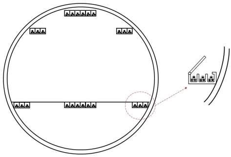
Figure: Example of tray installation for fibre optic/wire on aircraft
This tray installation concept from FBW system will give more advantage for FBL system due to the reduction of the numbers of interconnects making FBL configuration more practical and effective.
- CONDUIT ASSEMBLY
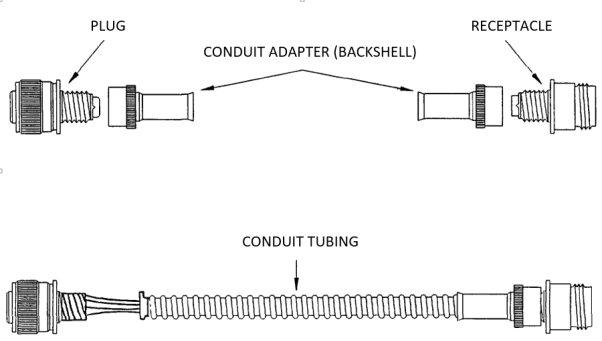
All of MDA-TA/DAC production aircraft utilized conduit assembly which is basically a clear tubing. The main purpose of this conduit is to provide extra security to the cables where work is done on a tight spacing and less work area. If the conduit is accidently bent, the tubing will always maintain a safe bending radius and prevent any physical damage to the cables. The tubing is also lightweight and very durable which adds another advantage. Using the conduit assembly, hybrid configuration may be achieve by combining both electrical and fibre optic cable into a same conduit. The following figure will show the examples of conduit assembly as MDA-TA/DAC are using on their production aircraft.
FIGURE: Flexible Conduit for Fibre Optic Installation
- ACTIVE OPTICAL CONTACT
Active Optical Contact or AOC is an active optical device that is embedded into the electrical contact point or connector shell. This type of installation basically use standard electrical connectors but inside the connectors, the electrical signal from transmitter is being converted into light signal and send through fibre optic cable which will reach the end of the cable in the form of light signals. This light signals then will be converted into electrical signal inside the receiver connectors which also have the embedded optical device. The AOC will act as the connector between two electrical signal port that is the transmitter and the receiver but will be sending the signal in the form of light signal via fibre optic cable. This results in no optical contact between transmitter and the receiver thus eliminating the need of extra devices at the end of both port to convert light signal into electrical signal.
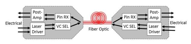
FIGURE: Active Optical Contact
FIGURE: Example of AOC working principle (https://www.slideshare.net/allanlee/sfp-trrx-selection-guidejan2014)
- AVIONIC MULTIFIBER ARRAY CONNECTOR (AVMAC)
Multifiber Array Connector II or MACII that was being use is going to be replace with the new Avionic Multifiber Array Connector or AVMAC. The new AVMAC was developed with AT&T with the purpose of upgrading the old MACII for fibre optic connection. The main function of new AVMAC is to be the termination point of fibre optic ribbon assembly. Ribbon fibre is basically a group of fibres, 12 or 18, arranged into a linear array. This ribbon fibre will be jacketed, wrap with buffer coat and strength member which will be very similar to the single channel fibre as MDA/TA-DAC approved. The AVMAC is a device which will connect the array of fibre in the ribbon to hold each individual fibre so that it can be align and easier to install 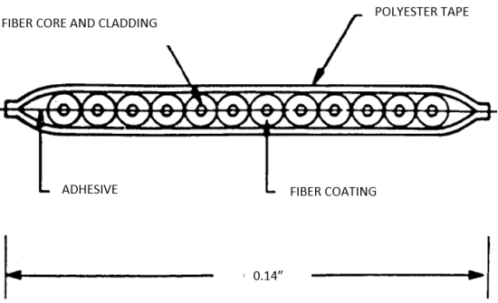
to the other mating half.
Figure: Cross-sectional of ribbon fibre assembly which consist of 12 fibre optic cables.
- SPLICES
During maintenance and installation, fibre optic needs to be splice to fit. After testing several fibre optic mechanical splices and only two mechanical splices that achieved MDA/TA-DAC approval. Although the two mechanical splices is considered to date fit their installation and maintenance approach, it is still cannot withstand the aircraft environment and none is consider as the right mechanical splices for aviation grade quality. The reasons for this result came from several points of the disadvantage of using market-ready mechanical splices in aircraft environment. First reason, fibre optic cable need to remove the buffer and the strength member in order to do splicing. If the buffer and strength member removed from the cable, every mechanical protection for the glass fibre ends at the splicing. Second, having the glass fibre exposed to the atmosphere, moisture in the air will get into the micro-cracks that naturally exist and will further expand the severity of the cracks into larger cracks. Increase in optical power loss as the micro-cracks elongated and propagated. Lastly, apart from previous problems with market-ready mechanical splices, it is also imposed a fire hazard due to this fusion splicing creates spark while being use on aircraft. Regulation made it clear that any devices that create spark or open flame are not permitted on fuelled aircraft. Due to the disadvantages mentioned, MDA-TA has develop their own designs for their fibre optic mechanical and chemical bond splices.
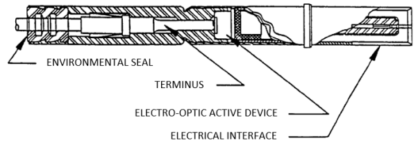
The new invention of splices/connectors would be a small, one piece construction that is lightweight and could withstand aircraft environment. The new connectors that were design with environmentally sealed construction should be accepting a single mated pin and socket termini for either fibre optic cable or standard copper wire. The connectors is very adaptable and can be install anywhere directly onto fibre optic cable that might need repairs such as a splices, modification or maintenance purpose. Next figure will show the example of the newly design connectors to fit aircraft usage and regulation.
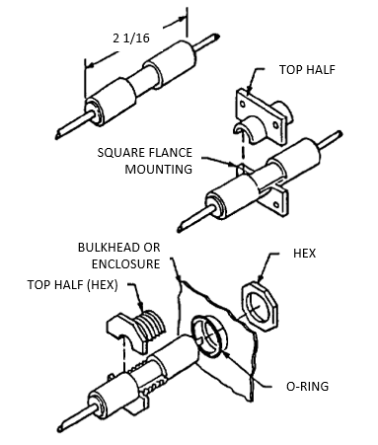
Figure: Fibre Optic/ Electrical Single-Channel Splice/ Connector/ Feedthrough
Contents
2.2 FLY-BY-LIGHT AS NEW EMERGING TECHNOLOGY FOR AIRCRAFT SYSTEM
2.2.1 Advantages of using fibre optic cables over copper cables
2.2.2 INSTALLATION OF FIBER OPTIC CABLE ON AIRCRAFT
2.2.2 FLASH PROGRAM FOR RESEARCH AND DEVELOPMENT
Cite This Work
To export a reference to this article please select a referencing stye below:
Related Services
View all


DMCA / Removal Request
If you are the original writer of this essay and no longer wish to have your work published on UKEssays.com then please click the following link to email our support team:
Request essay removalRelated Services
Our academic writing and marking services can help you!
Freelance Writing Jobs
Looking for a flexible role?
Do you have a 2:1 degree or higher?
Study Resources
Free resources to assist you with your university studies!