Flow of a Free Air Jet Laboratory Exercise
| ✅ Paper Type: Free Essay | ✅ Subject: Engineering |
| ✅ Wordcount: 2440 words | ✅ Published: 31 Aug 2017 |
An investigation into the structure of a free air jet and how its velocity is distributed during interaction with its surroundings
Air jets have provided the basis for jet propulsion mechanisms, commonly used to provide movement in jet engines, spacecraft and even particular marine animals. In aviation, it is important to measure an aircraft’s velocity, altitude and Mach number in order to monitor performance and determine areas of improvement. In this experiment, a pitot-static tube system was set up along the axis of a free air jet, and the local velocity of the air jet was calculated and recorded using measurements from an inclined manometer as the pitot-tube was displaced in both the horizontal and vertical planes. The experimental and theoretical results highlighted the same trends, confirming the expectation that as  decreased (due to increased displacement), local velocity,
  , also decreased. A divergence angle of 10.1° was calculated, and the volume flow rate varied between 0.0149 m3s-1 and 0.049 m3s-1.
An air jet is ‘a nozzle or tube from which a directed pressurised jet of air is emitted.’ (1) These have provided the basis for jet propulsion – producing a thrust in the opposite direction of the jet – as demonstrated through Newton’s third law. Airs jets are commonly used to provide movement in jet engines and spacecraft, and even certain marine animals have evolved to rely on jet propulsion mechanisms. (2) There are two main types of jet; impinging and free. While an impinging jet is directed towards a surface, this experiment is concerned with the interactions of a free, submerged air jet, where the jet is discharged into an ambient fluid of similar physical properties. (3)
A pitot tube is a pressure measurement instrument used to measure fluid flow velocity. (4) This is done by converting the kinetic energy of the flow into potential energy (5). Pitot-static systems, consisting of a pitot tube, a static port and the necessary measuring instruments (6), are often used in aviation to determine an aircraft’s velocity, altitude and Mach number, as well as having nautical applications in the calculation of boat and vessel speeds. (7)

3.1 Velocity
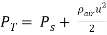
A pitot static tube measures two separate pressures: the stagnation pressure, , and the static pressure,
 (8) Bernoulli’s equation states that the total stagnation pressure is equal to the sum of the static pressure and the dynamic pressure,
  . The dynamic pressure is proportional to the density of the concerned medium,
  , and the square of the local velocity, v, such that:
 (equation 1)
If the pressure difference between the stagnation pressure and static pressure is applied to alter the water level of a manometer, equilibrium is achieved when:
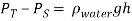 (equation 2)
Therefore, by combining equation 1 and equation 2, and assuming = 1.225 kgm-3 and  = 1000 kgm-3, the local velocity in ms-1 can then be calculated through the relationship:
 (equation 3)
3.2 Flow Rate
The volume flow rate leaving the nozzle of a circular air jet,  can be considered equal to exit velocity,
  , multiplied by nozzle surface area, A. (9) This relationship is represented through the equation:
 (equation 4)
Beyond the nozzle exit, the velocity cannot be considered constant at all vertical points in the jet; therefore, it is necessary to integrate to find the volume flow rate.

The expanded profile of the air jet can be considered circular, consisting of a series of annuli areas containing an air flow rate equal to  for each respective measured value of velocity and calculated area. This is represented visually in figure 1 below.
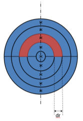

Recalling the area of an annulus as , where
  is the radius along the mid-point of the annulus, and considering the asymmetrical profile of the final jet requires separate measurements in each hemisphere, the total volume flow rate can be calculated through:
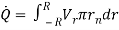
 (equation 5)
Here,  is the local velocity at the required radius and
  is the area of half an annulus, where
  is the radius at which the velocity was measured.


 Apparatus
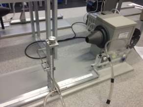
Nozzle of diameter 30mm, to create the uniform circular jet of air to be measured.
Pitot-static tube system, consisting of a pitot-tube, static tube and axial scales,to collect the air from the nozzle and carry it to the manometer.
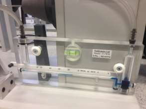
Manometer, inclined at an angle, θ, which holds the liquid and allows for its movement depending on the pressure apparent from the pitot-static tube system.
A zero, to locate the starting point at which measurements of the fluid distance along the manometer will be taken from.
A ruler, to manually measure the distance travelled by the liquid along the manometer,  .
.
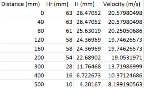
The zero was adjusted along the manometer to indicate the point at which further measurements with the ruler would be taken from and the pitot-static tube was moved along the apparatus to the origin, at the centre of the nozzle, where the coordinates corresponded to (0, 0). The air jet was turned on and, after allowing sufficient time to warm up, the distance the liquid had moved along the manometer,  was measured, using the ruler, and recorded. The tube was then moved along the centreline across a series of predetermined distances away from the air jet (see Appendix A) up to 500mm – the point (500,0) – and was again measured and recorded at each interval.
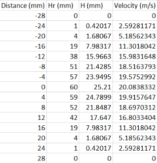
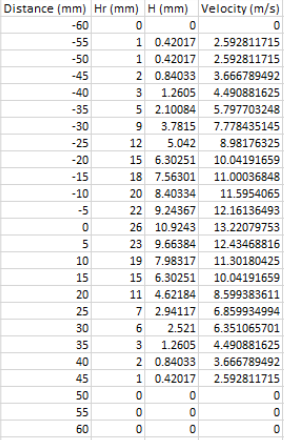
The pitot-static tube was then returned to sit 60mm away from the air jet and lowered to a vertical height of -28mm from the origin where was again measured and recorded. Maintaining an axial distance of 60mm, the pitot-static tube was then raised in increments of 4mm up to a maximum height of 28mm and the distance, , measured for each step. This experiment was then repeated at axial distances of 180mm and 300mm, through ranges of -50mm to 50mm and -60mm to 60mm respectively, using increments of 5mm in both.
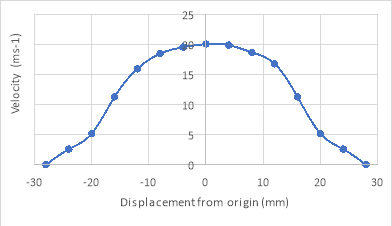
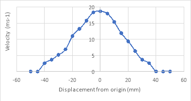
5.1 Velocity Profiles
 The recorded distances,
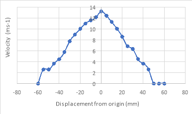
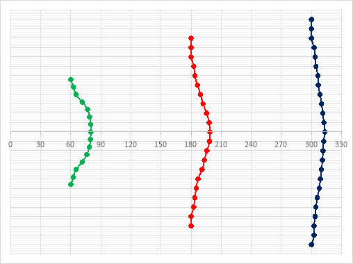
 , for the three vertical experiments, were then converted into vertical distances, h; in this experiment, θ = 13°. The velocities at each height were then calculated using equation 3 and graphs of velocity against height for all three axial distances were drawn as shown in figures 3a, 3b and 3c below.


5.2 Plan View


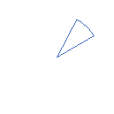


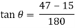
The divergence angle can be calculated by forming a triangle between the edge of the jet and a line perpendicular to the nozzle boundary; see figure 4. For this experiment:

5.3 Centreline Velocity Distribution
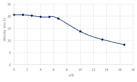
The recorded distances, , for the centreline experiment were converted into vertical distances, h, using θ = 13°. The axial distance, x, was then divided by the nozzle diameter, D = 30mm, and a graph of velocity against  was plotted, as seen below in figure 5.

5.4 Volume Flow Rate
Assuming is constant at the edge of the nozzle, the exit volume flow rate can be calculated through equation 4:
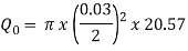
 m3s-1
m3s-1
Beyond the nozzle exit, values for , the annulus width, and , the outer radius, were required to calculate volume flow rate. The values for
  were 4mm at an axial distance of 60mm, and 5mm at axial distances of 180mm and 300mm, and values for corresponded to the radial distances; these can be found in Appendices B, C and D.
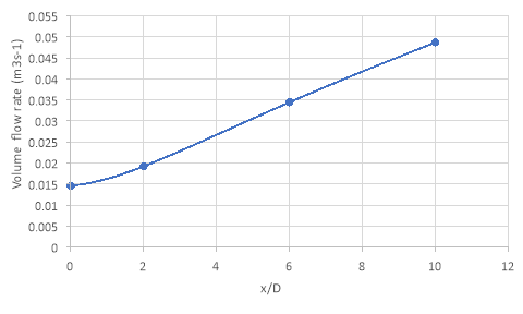
 Using equation 5, the volume flow rates were found at x = 2D, x = 6D and x = 10D respectively, and the results displayed through table 1.
|
Axial Distance (mm) |
Volume Flow Rate (m3s-1) |
|
60 |
0.01925 |
|
180 |
0.034475 |
|
300 |
0.048705 |
A graph of volume flow rate against axial distance was then plotted for comparison; see figure 6 below.

6.1 Structure of the Air Jet
An air jet is comprised of three important regions: the core, the mixing region and the edge or boundary. Within the core, the velocity does not vary significantly from the nozzle exit speed. From the measurements in this experiment, this region exists up to around 180mm along the centreline (see figure 5). Outside of the core, illustrated in figure 4, the mixing region is encountered. Throughout this region, the local velocity, , is less than the exit velocity,
  , due to the reaction of the air jet with the ambient fluid. The edge or boundary of the jet represents the radial distance at which the local velocity is equal to zero at each centreline distance. The edge of the jet increases linearly at a rate dependent on the divergence angle, measured to be 10.1° in this experiment. This is similar to the universal value for the divergence of a jet of 11.8°, which is independent of nozzle diameter, discharge speed or the medium involved. (10)
6.2 Diameter of the Air Jet
From the plan view illustrated in figure 4, it can clearly be seen that the air jet spreads out as axial distance increases. This occurs as a consequence of the significant velocity difference between the jet and the ambient fluid, which creates a highly unstable shear layer at the edge of the jet. This shear layer is subject to large variance in local velocities, generating strong turbulent fluctuations which subsequently entrain the ambient fluid into the path of the jet, increasing the mixing of the two fluids. As a consequence of both the turbulent fluctuations and the entrainment of the ambient fluid, the shear layer continues to be pushed outwards as the jet flows downstream. (11)
6.3 Centreline Volume Distribution
Figure 5, above, clearly illustrates that up to a value of = 6, the velocity along the centreline varies very little, with a range of 0.833 ms-1. This region is known as the core, where . The only source of momentum when the jet exits the nozzle is from the jet itself, as the surrounding fluid is at rest. The absence of external forces acting on the jet suggests that the centreline velocity will remain constant as distance increases. (11) Beyond an axial distance of 180mm, the velocity follows an inversely proportional relationship with distance, decreasing at a rate of
  (where k is an unknown constant). This occurs when the core of the jet interacts with entrained ambient fluid caused by significant velocity fluctuations at the edge of the jet, decreasing the velocity of the fluid as discussed in section 5.2. Due to the interaction between two different fluid flows, the region in which this occurs is referred to as the mixing region.
6.4 Volume Flow Rate
Figure 6 suggests that volume flow rate increases linearly with axial distance, rising from 0.015m3s-1 at the nozzle exit to 0.049m3s-1 at an axial distance of 300mm. From section 4.4, it is known that the volume flow rate is a function of the jet area and local velocities across the diameter. Due to conservation of momentum, it is expected that as the area increases, the velocity decreases such that the volume flow rate remains constant across all axial distances. However, the increase in volumetric flow is a result of entrainment of the stationary surrounding fluid. The turbulent flow caused by the velocity fluctuations in the shear layers contributes to an increased local velocity across the diameter of the jet, increasing volume flow rate.
6.5 Experimental Errors and Uncertainties
Although this experiment has successfully demonstrated the characteristics of a free air jet as highlighted in this discussion section, numerous errors and uncertainties were still encountered throughout the experiment which could have had a potentially significant effect on the results obtained. One of the most common sources of uncertainty was the use of a ruler to measure the distance of the fluid along the manometer. This combined human error, due to the estimation of both the ‘zero position’ and the final position of the fluid meniscus with systematic error, as a consequence of the ruler measuring with an uncertainty of ±1mm and therefore, accurate measurements for were not obtained. Similarly, the location of the necessary axial and radial positions for the pitot-tube were subject to a similar human error. The fluid in the manometer also contained several air bubbles prior to the experiment; this is a systematic error as it would subsequently affect every manometer distance reading. Therefore, it is possible that the results obtained for could consistently higher than expected due to the presence of these air bubbles in the fluid. The final significant error involved in this experiment was the random error associated with the changing position of the static tube. For a set axial and radial positioning of the pitot-static tube, changing the height and geometry of the static tube caused the manometer reading to alter slightly as well. Although efforts were made to maintain the location of this tube, there is still the possibility it could have caused sporadic errors in the results.
To conclude, the experiment outlined in this report was successful in demonstrating the interactions of a free air jet with an ambient fluid and, subsequently, the effects of the displacement of the pitot-tube on the local velocity along the centreline and throughout the mixing region. The decreasing local velocity as displacement increased was found to be a result of turbulent fluctuations causing entrainment of ambient fluid into the path of the jet.
In the experiment, the maximum velocity was found to be around 20ms-1 for a distance of 180mm along the centreline of the jet and the divergence angle was calculated to be 10.1°. These results were useful in introducing the basic structure of an air jet, which comprises of three main regions: the core, the mixing region, and the edge. The slight discrepancy between the measured divergence angle and the universal angle of 11.8° (9) can be considered due to the inaccuracy in measuring the position of the fluid meniscus in the manometer using a ruler, producing potentially unreliable results.
The findings from this experiment are statistically insignificant due to the nature of the apparatus used and the various possible sources of error, both systematic, due to air bubbles present in the manometer fluid, and human, arising from the use of a ruler for distance measurements. However, the experiment was useful in demonstrating the interactions of an air jet with its surroundings, as well as introducing the concept of internal structures within a free air jet.
|
[1] |
Oxford Dictionaries, “Air Jet,” [Online]. Available: https://en.oxforddictionaries.com/definition/air_jet. [Accessed 24 March 2017]. |
|
[2] |
LearningInfo, “Which Animals use Jet Propulsion,” [Online]. Available: http://www.learninginfo.org/sandbox/which-animals-use-jet-propulsion.htm. [Accessed 25 March 2017]. |
|
[3] |
W. Grassi, “Impinging Jets,” 2 February 2011. [Online]. Available: http://www.thermopedia.com/content/872/ . [Accessed 24 March 2017]. |
|
[4] |
Wikipedia, “Pitot Tube,” [Online]. Available: https://en.wikipedia.org/wiki/Pitot_tube. [Accessed 25 March 2017]. |
|
[5] |
Efunda, “Pitot Tubes Theory,” [Online]. Available: http://www.efunda.com/designstandards/sensors/pitot_tubes/pitot_tubes_theory.cfm. [Accessed 26 March 2017]. |
|
[6] |
P. Willits, Guided Flight Discovery – Private Pilot, Jeppesen Sanderson, 2004. |
|
[7] |
S. Houston, “Pitot Static System,” 13 October 2016. [Online]. Available: https://www.thebalance.com/aircraft-systems-pitot-static-system-282605. [Accessed 26 March 2017]. |
|
[8] |
I. Gursal, “Flow of a Free Air Jet,” University of Bath, Bath, 2017. |
|
[9] |
Khan Academy, “What is Volume Flow Rate,” [Online]. Available: https://www.khanacademy.org/science/physics/fluids/fluid-dynamics/a/what-is-volume-flow-rate. [Accessed 27 March 2017]. |
|
[10] |
Dartmouth College, “Turbulent Jets,” [Online]. Available: https://thayer.dartmouth.edu/~d30345d/books/EFM/chap9.pdf. [Accessed 24 March 2017]. |
|
[11] |
Anon, “Jet,” [Online]. Available: https://www.eng.fsu.edu/~shih/succeed/jet/jet.htm. [Accessed 29 March 2017]. |
Cite This Work
To export a reference to this article please select a referencing stye below:
Related Services
View all


DMCA / Removal Request
If you are the original writer of this essay and no longer wish to have your work published on UKEssays.com then please click the following link to email our support team:
Request essay removal