Elements of Multi-Study Building Design
| ✅ Paper Type: Free Essay | ✅ Subject: Architecture |
| ✅ Wordcount: 2139 words | ✅ Published: 03 Nov 2020 |
Question 1
Task 1
Base isolation is a Passive structural control technique which has a collection of structural elements used to decouple the structure from its foundation resting on shaking ground and protects structure integrity. Active base isolation is used to take almost benefits of passive base isolation. To control performance at a constant level of floor acceleration by helping active base isolation. New Zealand is a leader in base isolation techniques an in 1970’s Base isolator bearings were pioneered in New Zealand by Dr Bill Robinson. It works by separating the structure from the ground and the lateral forces of an earthquake. Base isolation is of two types elastomeric and sliding. These two are designed to take the weight of the building and let the foundations move sideways during an earthquake force. Flexible elastomeric bearings have layers of bonded rubber and steel with a central lead core. Lead core softens when it goes under pressure and absorb energy that would otherwise be transferred to the structure. Due to sliding system there is no energy absorption, just deflection through the bearings. Along with both types of base isolation, structure movement during an earthquake is reduced, means less risk of damage. Base isolation absorbs the earthquake’s energy and improves the seismic performance of a tall buildings. Lead Rubber Bearings consists of a laminated rubber and steel bearing with steel flange plates for mounting to the structure. Isolators have an energy dissipating lead core. Rubber in the isolator acts as a spring. Rubber is very soft laterally but very stiff vertically. The high vertical stiffness is achieved by having thin layers of rubber reinforced by steel shims. These two characteristics allow the isolator to move laterally with relatively low stiffness yet carry significant axial load due to their high vertical stiffness. The lead core provides damping by deforming plastically when the isolator moves laterally in an earthquake. (CCANZ, n.d.). There are many types of Damping devices which can absorb energy and add damping buildings to reduce seismic response which comes during earthquakes. Damping devices can be combined with base isolation or can be placed at the height of structure. Damping devices especially used for tall buildings where base isolation is not so effective alone. As compared to low-rise buildings, their horizontal displacement needs to be controlled and this can achieve by damping devices, which absorb a good part of energy making the displacement to be controlled.
Task 2
The most conventional approach to achieve seismic isolation is by increasing the ductility of the building or by increasing the elastic strength of the structure. The engineer who is given the job to design the structure needs to increase the capacity to facilitate the capacity of the demand. However base isolation technique uses a different way of approach. This approach of this method is to minimise the seismic demand rather than increasing the capacity of the structure.
Museum of New Zealand at Te Papa Tongarewa is the true example of Seismic base isolation technology shown in figure 1. Base isolation technology increased the probability of structural integrity to be remain retained and occupants remains unharmed, this technology also helps the structure to remain operational.

Figure 1 Museum of New Zealand, Te Papa Tongarewa (Meccanico, 2017)
Another benefit of using this technology is that it increases the value of property because Te Papa Tongarewa is an earthquake prone area. This technology is used for reinforced structures and stone or brick type masonry structures. Base isolation technology for this structure is results in high success as the structure remained fully operational after February 2011 earthquakes. (Meccanico, 2017).
Question 2
Task 1
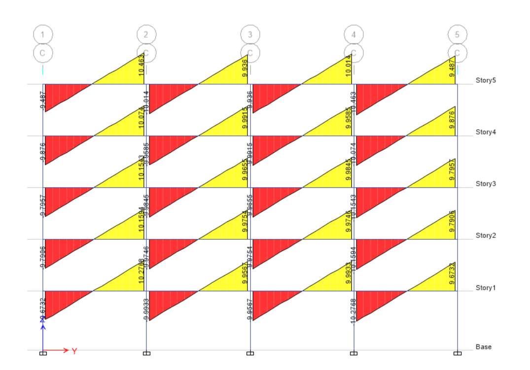
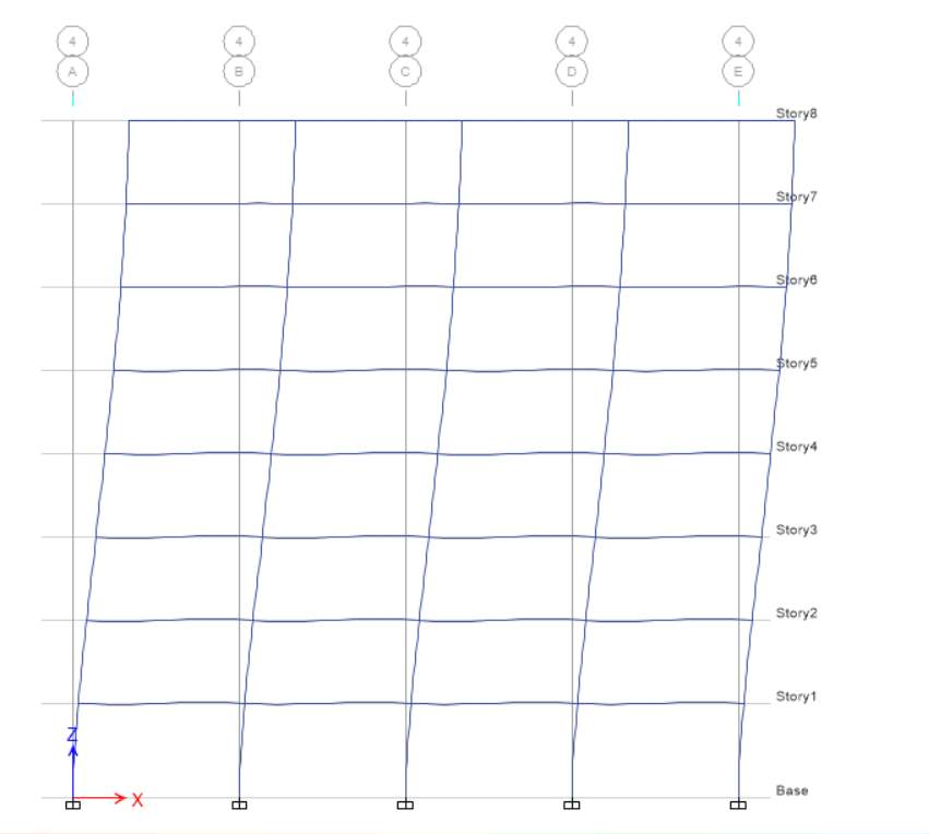
In this task, Scenario A is considered in which spacing of grids in X and Y direction is 5m. For this scenario I choose concrete rectangular column of 500mm width and 500mm depth and beam of 400 mm width and 300mm depth with permanent load of 5 kPa and Imposed load is 5 kPa. Based on the parameter given the axial force diagram for elevation C is shown below.
Axial force depends upon the tributary area as for both extreme column 1 and 5 the tributary area is less and hence the axial force is also less as compared to column 2, 3 and 4 where axial force is more as tributary area is more. The axial force is more for bottom storey as compared to top storey as shown in figure axial force increases from top to bottom.


Task 2
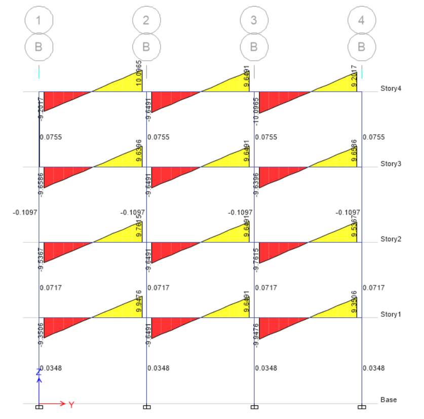
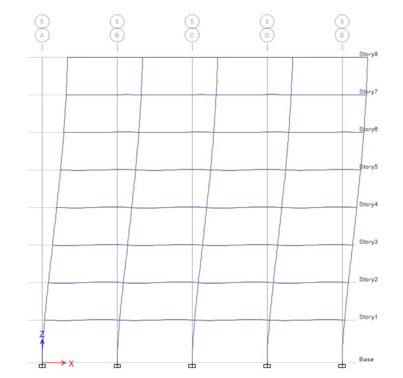
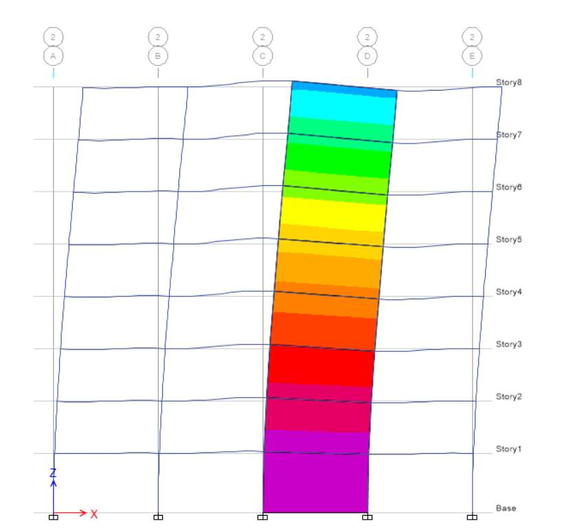
In this task, Scenario B is considered in which spacing of grids in X and Y direction is 7m. For this scenario I choose concrete rectangular column of 350mm width and 350mm depth and beam of 400 mm width and 300mm depth with permanent load of 5 kPa and Imposed load is 5 kPa. Based on the parameter given the shear force diagram for elevation C is shown below. It is seen that shear force value corresponding to all column is nearly same whereas its decreasing from column 1 to column 5. Shear force is nearly same because of the uniform load for all storeys. For column 1 and column 5 shear force is same because of uniform load.
Task 3
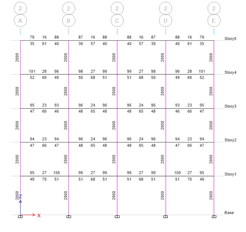
Scenario A Elevation 2

Scenario B Elevation 2

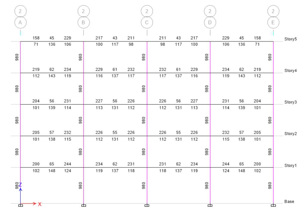
(a) At elevation 2, the longitudinal bars for both scenarios are different. In scenario A, there is fat column which has highest value as compared to slender column. For scenario A, the value is 2000 whereas for scenario B the value is 980 as it depends upon the longitudinal bars and size of the column. In both scenario I choose different size of column.
(b) The longitudinal bars area is different when there is different size of column because of column size and axial load which is applied to column. In fat column, the size of column is more and more load applied to it because of stability and it can decrease the stress for required column. Stress depends upon the size of column if size of column is more it can handle more stress otherwise less stress suitable for small column size.
Question 3
Task 1
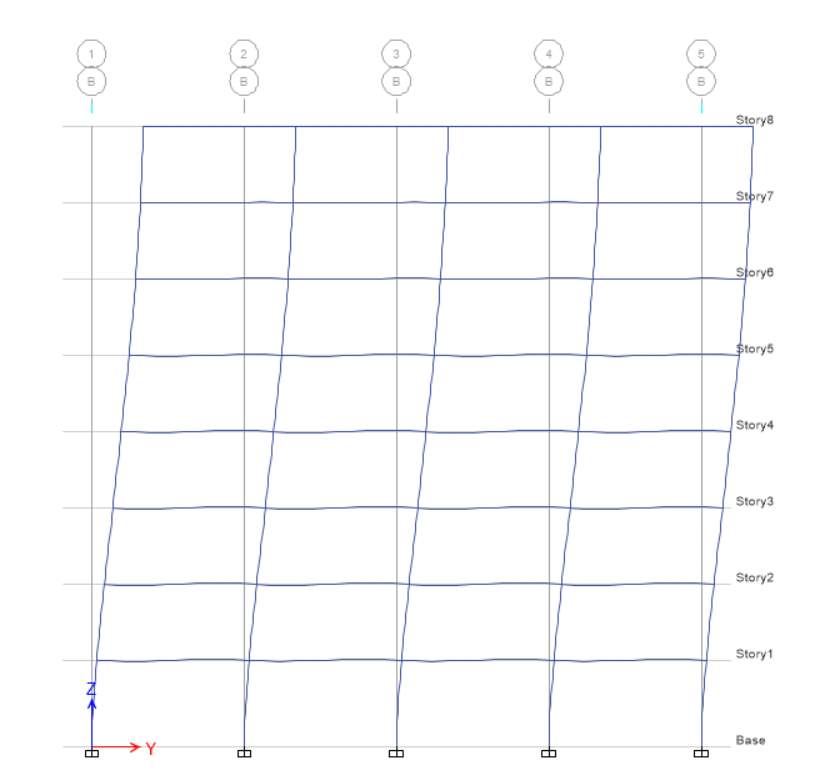
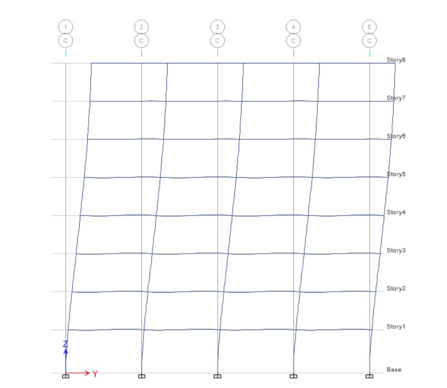
(a) Elevation A

Elevation B

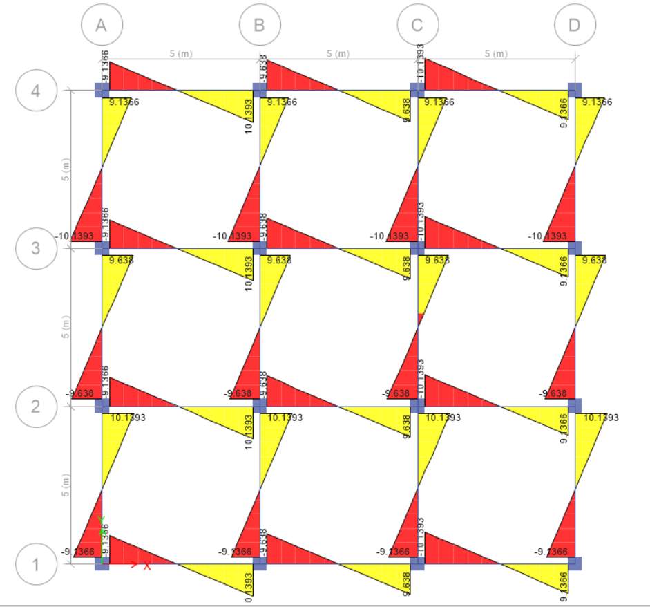
(b) Elevation A and Elevation B is shown for Scenario A for the shear force diagram. In both the elevation there is difference in the values for same structures. For elevation A and B there are different values in negative because of more tributary area and load is not on the beam whereas in elevation A half load is on the beam and less has tributary area. In elevation A, half load distributed on beams and elevation B has dead load which is doubled.
Task 2
(a) Scenario B Elevation A

Scenario B Elevation B
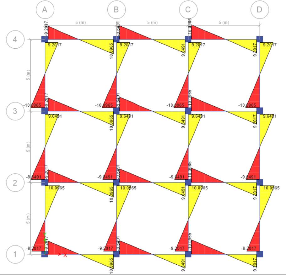
(b) The above 2 elevation is for two-way slab in which the load is equally divided on the beams and the value for shear force decreases in two-way slab as compared to one-way slab. Elevation A shows that the tributary area of slab is less as compared to elevation B because in elevation B all the loads distributed on slab surrounding beams. Two-way slab shows less shear force in both elevation as compared to one-way slab for both elevations.
Task 3
STOREY 1 SCENARIO A
STOREY 2 SCENARIO B
(a) For scenario A, I choose storey 1 and for scenario B, I choose storey 2. Shear force for scenario A is more because of one-way slab in which reinforcement is applied on both direction and it passed load on two opposite side with the help of beams.
(b) In both scenario there is difference in slab, in first scenario there is one-way slab whereas in second system there is two-way slab. In two-way slab shear force is less because slab is supported by the beams on all the four sides and load carried in both directions. In scenario A the load is carried along one direction.
Question 4
Task 1
E-X

E-Y


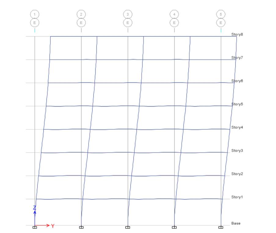
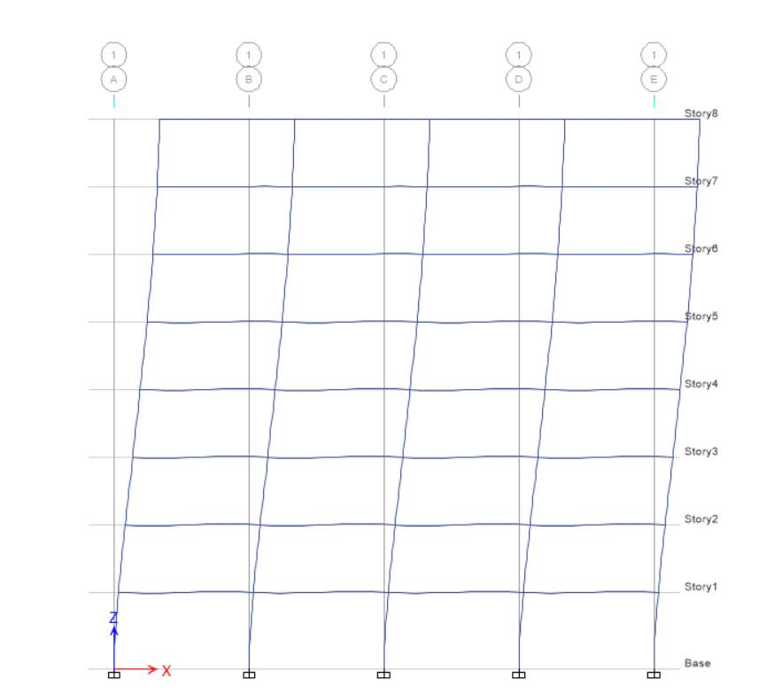
For EX at elevation 1, displacement and drift are equal to zero whereas height is 3500 mm for base level, while for level 1 displacement is 9.18 and height is 3500 mm, drift for level 1 is
2 (2 – 1) / H2
(9.18 – 0) / 3500
0.00262285
Task 2
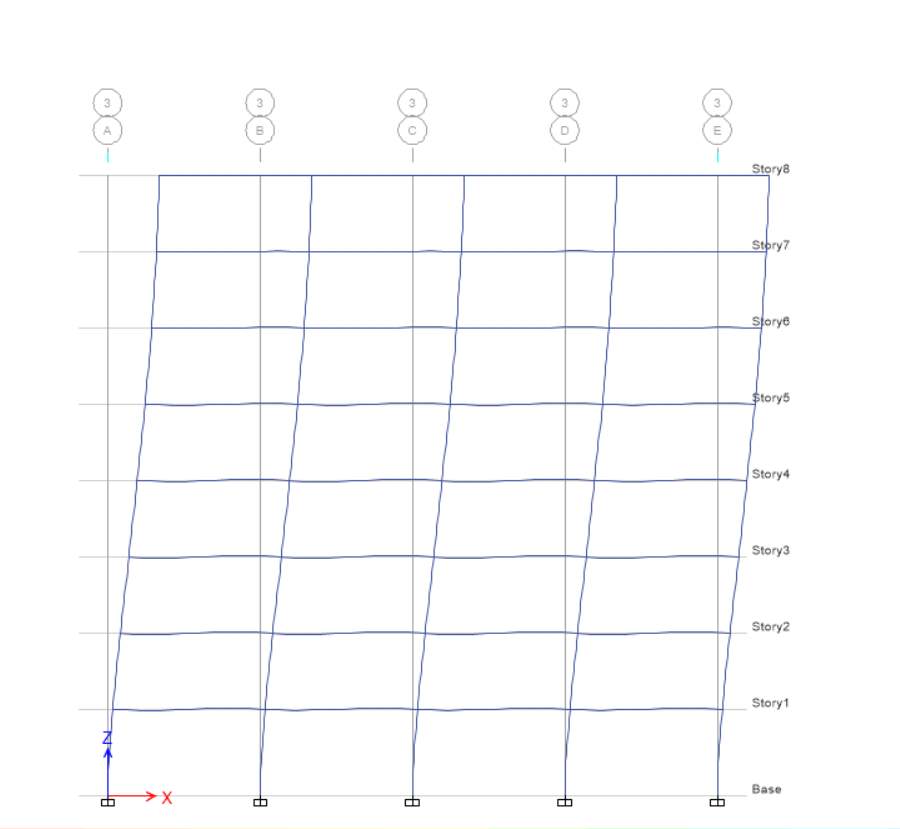
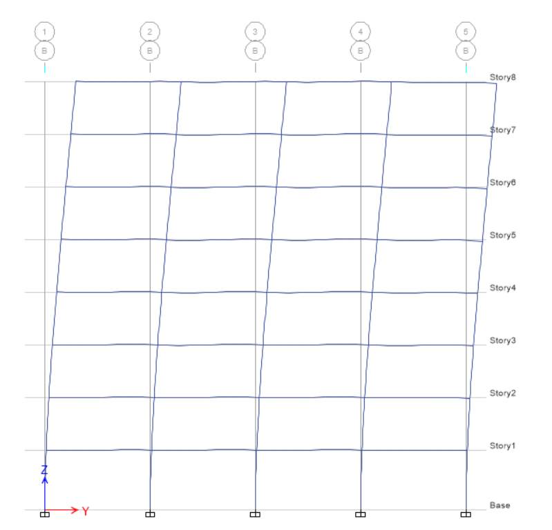
E-Y

For EY at elevation 1, displacement and drift are equal to zero whereas height is 3500 mm for base level, while for level 1 displacement is 9.32 and height is 3500 mm, drift for level 1 is
2 (2 – 1) / H2
(9.32 – 0) / 3500
0.00262885

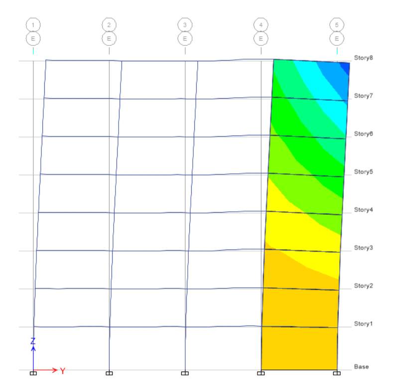
E-X 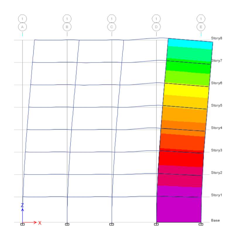


Question 5
Task 1
Literature review of paper Innovation techniques for concrete reinforcement with polymers. This task will cover problem discussed in paper, background summary and specific points covered in paper.
1. Problems
The main problem addressed by author is the steel reinforcement as it gets corroded under external atmospheric affects and degrades construction. This is the biggest problem as it is important to keep concrete buildings reliable for long period and it’s not possible with steel reinforcement. Bond deterioration between concrete and steel reinforcement is the main reason of corrosion.
2. Summary
The paper highlights that the drawbacks of concrete were overcome by introducing steel reinforcement for building design to improve the concrete low tensile strength. Also waste material recycling process is discussed to overcome the above problem. This paper shows the use of polyethylene terephthalate (PET) and carbon fibre reinforcement polymers (CFRP) at place of steel in concrete elements. This paper shows the waste material study.
3. Authors Points
Author performed testing on concrete beam reinforced with PET and CFRP to use waste material. Reinforced made up with PET and CFRP as continuous bars and strips by putting these elements inside the concrete beam. Author performed this testing to reduce corrosion and to reduce the cracking in concrete structure as the ductility and resistance of these material are good to overcome atmosphere affects.
Task 2
In this task we will discuss the diagram for PET reinforcement and CFRP reinforcement. Figure 15 and figure 16 represents the positioning of PET bars inside the reinforcement steel cage of specimen and positioning of CFRP strips inside steel cage of specimen respectively. PET bars specimens compiled by reversing the vibrated concrete in framework and disarmed after 30days to perform testing as shown in figure 2. In case of CFRP strips, two bars arranged in upper side and two arranged in lower side of specimen. In this after fixing stirrups to cage, first vibrated concrete layer of 20mm thickness applied. After that CFRP layer is applied and then again 20mm vibrated concrete layer and then second layer of CFRP as shown in figure 3 (Foti, 2016).
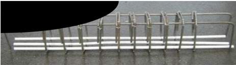
Figure 2 PET bars position (Foti, 2016)
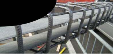
Figure 3 CFRP strips position (Foti, 2016)
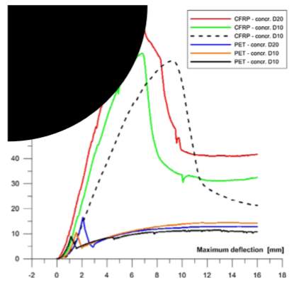
Figure 4 Bending test results for six specimens (Foti, 2016)
After 30 days bending test performed to calculate maximum failure load, test performed at constant speed. Some cracks show specimen behaviour as for PET bars got more crack. Figure 4 shows the six specimen and each test carried out by applying forces and corresponding values of maximum deflection at central section of the beam (Foti, 2016).
So, it is analysed that specimen with PET bar realized with more load’s failure than CFRP as it has wide contact surface with respect to bars.
Task 3
1. Result summary
It is concluded that the use of PET and VFRP reduces the cracks and corrosion process for reinforced concrete structure buildings. CFRP strips gave the better result for bending inside the concrete for supported load.
Whereas in case of PET, the results are not good as were expected as the area of reinforced is reduced and shape of bars have low adherence to concrete as compared to strips. But it uses the waste material and provided good results.
Overall, PET can be used in substitution of welded steel mesh in case of high moisture areas and where operational loads are low. CFRP used as a steel reinforced substitute for bending elements.
2. Meaning of results
The results show that the reinforced made up with PET and CFRP by arranging both inside the elements as strips and bars to reduce the cracks and to reduce the corrosion affects under atmospheric conditions.
3. Weakness
Reinforcement with PET and CFRP did not performed same results as it was expected. Reinforcement wit CFRP strips is higher than with PET bars as got higher level of cracking.
4. Future scope/ Next step
There is need to utilize CFRP strips and PET in form of strip inside the concrete beam as reinforcement by making extra tests on behaviour of fibre reinforcement for structural elements.
There is need to make one more comparison between CFRP strips and PET bars to analyse the behaviour of same concrete beams with same reinforcement quantity and same contact surface to concrete.
References
- CCANZ. (n.d.). Retrieved from ccanz.org.nz: https://www.ccanz.org.nz/page/Base-Isolation.aspx
- Foti, D. (2016). Innovative techniques for concrete reinforcement with polymers. Construction and building materials, 202-209.
- Meccanico. (2017). Seismic Base Isolation. Retrieved from Meccanico.co.nz: http://meccanico.co.nz/services/seismic-base-isolation
- Omiya, M., Sano, W. & Kitamura, H., (2018). Influence of performance variation of seismic isolation devices due to long-period ground motion on response characteristics of base isolated building-Response evaluation of base isolated building using representative base isolation devices. AIJ Journal of Technology and Design, 24(58), pp.963-968. https://tus.elsevierpure.com/en/publications/influence-of-performance-variation-of-seismic-isolation-devices-d
Cite This Work
To export a reference to this article please select a referencing stye below:
Related Services
View all


DMCA / Removal Request
If you are the original writer of this essay and no longer wish to have your work published on UKEssays.com then please click the following link to email our support team:
Request essay removal